SCDS001O November 1992 – September 2015 SN74CBT3244
PRODUCTION DATA.
- 1 Features
- 2 Applications
- 3 Description
- 4 Revision History
- 5 Pin Configuration and Functions
- 6 Specifications
- 7 Parameter Measurement Information
- 8 Detailed Description
- 9 Application and Implementation
- 10Power Supply Recommendations
- 11Layout
- 12Device and Documentation Support
- 13Mechanical, Packaging, and Orderable Information
Package Options
Refer to the PDF data sheet for device specific package drawings
Mechanical Data (Package|Pins)
- DGV|20
- DB|20
- DW|20
- PW|20
- RGY|20
Thermal pad, mechanical data (Package|Pins)
Orderable Information
9 Application and Implementation
NOTE
Information in the following applications sections is not part of the TI component specification, and TI does not warrant its accuracy or completeness. TI’s customers are responsible for determining suitability of components for their purposes. Customers should validate and test their design implementation to confirm system functionality.
9.1 Application Information
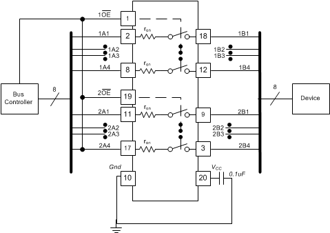
The SN74CBT3244 device can be used to control up to 4 bits with 2 channels simultaneously. The application shown in Figure 4 is a 8-bit bus being controlled. The OE pins are used to control the chip from the bus controller. This is a generic example and can apply to many situations. If an application requires fewer than 8 bits, ensure that the A side is tied either high or low on unused channels.
9.2 Typical Application
 Figure 4. Typical Application
9.2.1 Design Requirements
A 0.1-µF bypass capacitor should be placed between each VCC pin and GND. Each capacitor should be placed as close as possible to the SN74CBT3244 device.
9.2.2 Detailed Design Procedure
- Recommended input conditions:
- For specified high and low levels, see VIH and VIL in Electrical Characteristics
- Inputs and outputs are overvoltage tolerant, which allows them to go as high as 5.5 V at any valid VCC
- Recommended output conditions:
- Load currents must not exceed ±64 mA per channel
- Frequency selection criterion:
- Added trace resistance or capacitance can reduce maximum frequency capability; use layout practices as directed in Layout Guidelines
9.2.3 Application Curve
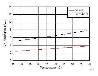
 Figure 5. ON-Resistance (Ron) Variation vs Temperature1