SBOS707B April 2014 – August 2014 TMP75C
PRODUCTION DATA.
- 1 Features
- 2 Applications
- 3 Description
- 4 Revision History
- 5 Pin Configuration and Functions
- 6 Specifications
- 7 Detailed Description
- 8 Application and Implementation
- 9 Power Supply Recommendations
- 10Layout
- 11Device and Documentation Support
- 12Mechanical, Packaging, and Orderable Information
Package Options
Mechanical Data (Package|Pins)
Thermal pad, mechanical data (Package|Pins)
Orderable Information
8 Application and Implementation
8.1 Application Information
The TMP75C is used to measure the PCB temperature of the location it is mounted. The programmable address options allow up to eight locations on the board to be monitored on a single serial bus. Connecting the ALERT pins together and programming the temperature limit registers to desired values allows for a temperature watchdog operation of all devices, interrupting the host controller only if the temperature exceeds the limits.
8.2 Typical Application
 Figure 18. Temperature Monitoring of Multiple Locations on a PCB
8.2.1 Design Requirements
The TMP75C only requires pull-up resistors on SDA and ALERT, although a pull-up resistor is typically present on the SCL as well. A 0.01-μF bypass capacitor on the supply is recommended, as shown in Figure 18. The SCL, SDA, and ALERT lines can be pulled up to a supply that is equal to or higher than VS through the pull-up resistors. To configure one of eight different addresses on the bus, connect A0, A1, and A2 to either VS or GND.
8.2.2 Detailed Design Procedure
The TMP75C should be placed in close proximity to the heat source to be monitored, with a proper layout for good thermal coupling. This ensures that temperature changes are captured within the shortest possible time interval.
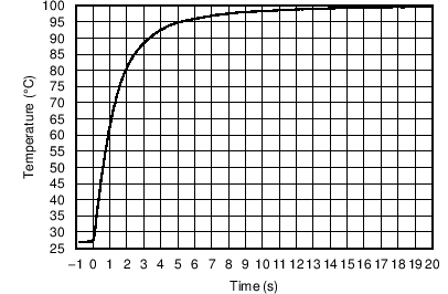
8.2.3 Application Curves
Figure 19 shows the step response of the TMP75C to a submersion in an oil bath of 100°C from room temperature (27°C). The time-constant, or the time for the output to reach 63% of the input step, is 1.5 seconds.