SLIS149 June 2014 TPL0102-EP
PRODUCTION DATA.
- 1 Features
- 2 Applications
- 3 Description
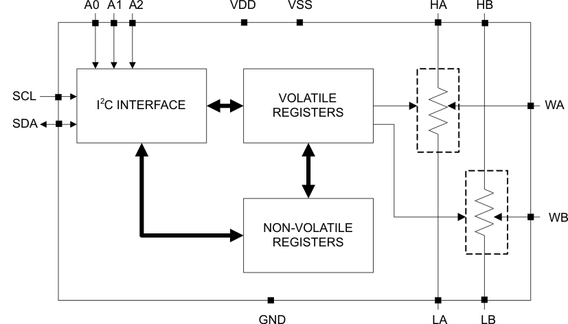
- 4 Functional Block Diagram
- 5 Revision History
- 6 Pin Configuration and Functions
- 7 Specifications
-
8 Detailed Description
- 8.1 Overview
- 8.2 Functional Block Diagram
- 8.3 Feature Description
- 8.4 Device Functional Modes
- 8.5
Register Maps
- 8.5.1 Slave Address
- 8.5.2 TPL0102-EP Register Maps
- 8.5.3 IVRA (Initial Value Register for Potentiometer A)
- 8.5.4 WRA (Wiper Resistance Register for Potentiometer A)
- 8.5.5 IVRB (Initial Value Register for Potentiometer B)
- 8.5.6 WRB (Wiper Resistance Register for Potentiometer B)
- 8.5.7 ACR (Access Control Register)
- 9 Application and Implementation
- 10Layout
- 11Device and Documentation Support
- 12Mechanical, Packaging, and Orderable Information
Package Options
Mechanical Data (Package|Pins)
- PW|14
Thermal pad, mechanical data (Package|Pins)
Orderable Information
1 Features
- Dual-Channel, 256-Position Resolution
- Non-Volatile Memory Stores Wiper Settings
- 2-mm × 2-mm, 14-Pin TSSOP Package
- 100-kΩ End-to-End Resistance (TPL0102-100)
- Fast Power-Up Response Time to Wiper Setting: <100 µs
- ±0.5 LSB INL, ±0.25 LSB DNL (Voltage-Divider Mode)
- 4 ppm/°C Ratiometric Temperature Coefficient
- I2C-Compatible Serial Interface
- 2.7- to 5.5-V Single-Supply Operation
- ±2.25 to ±2.75 V Dual-Supply Operation
- Operating Temperature Range From
–40°C to 125°C - ESD Performance Tested Per JESD 22
- 2000-V Human Body Model
(A114-B, Class II)
- 2000-V Human Body Model
- Supports Defense, Aerospace, and Medical Applications
- Controlled Baseline
- One Assembly and Test Site
- One Fabrication Site
- Available in Extended (Q) Temperature –40°C to 125°C
- Extended Product Life Cycle
- Extended Product-Change Notification
- Product Traceability
2 Applications
- Adjustable Gain Amplifiers and Offset Trimming
- Adjustable Power Supplies
- Precision Calibration of Set Point Thresholds
- Sensor Trimming and Calibration
- Mechanical Potentiometer Replacement
3 Description
The TPL0102-EP is a two-channel, linear-taper digital potentiometer with 256 wiper positions. Each potentiometer can be used as a three-terminal potentiometer or as a two-terminal rheostat. The TPL0102-EP-100 has an end-to-end resistance of 100 kΩ.
The TPL0102-EP has non-volatile memory (EEPROM) which can be used to store the wiper position. The internal registers of the TPL0102-EP can be accessed using the I2C interface.
The TPL0102-EP is available in a 14-pin TSSOP package with a specified temperature range of –40°C to 125°C.
Device Information(1)
| ORDER NUMBER | PACKAGE | BODY SIZE (NOM) |
|---|---|---|
| TPL0102-100QPWREP | TSSOP (14) | 5.00 mm × 4.40 mm |
- For all available packages, see the orderable addendum at the end of the data sheet.
4 Functional Block Diagram