SLVSFR1 August 2020 TPS25980
PRODUCTION DATA
- 1 Features
- 2 Applications
- 3 Description
- 4 Revision History
- 5 Device Comparison Table
- 6 Pin Configuration and Functions
- 7 Specifications
-
8 Detailed Description
- 8.1 Overview
- 8.2 Functional Block Diagram
- 8.3 Feature Description
- 8.4 Fault Response
- 8.5 Device Functional Modes
-
9 Application and Implementation
- 9.1 Application Information
- 9.2
Typical Application: Patient Monitoring System in Medical Applications
- 9.2.1 Design Requirements
- 9.2.2
Detailed Design Procedure
- 9.2.2.1 Device Selection
- 9.2.2.2 Setting the Current Limit Threshold: RILIM Selection
- 9.2.2.3 Setting the Undervoltage Lockout Set Point
- 9.2.2.4 Choosing the Current Monitoring Resistor: RIMON
- 9.2.2.5 Setting the Output Voltage Ramp Time (TdVdt)
- 9.2.2.6 Setting the Load Handshake (LDSTRT) Delay
- 9.2.2.7 Setting the Transient Overcurrent Blanking Interval (tITIMER)
- 9.2.2.8 Setting the Auto-Retry Delay and Number of Retries
- 9.2.3 Application Curves
- 9.3 System Examples
- 10Power Supply Recommendations
- 11Layout
- 12Device and Documentation Support
- 13Mechanical, Packaging, and Orderable Information
Package Options
Mechanical Data (Package|Pins)
- RGE|24
Thermal pad, mechanical data (Package|Pins)
- RGE|24
Orderable Information
8.4 Fault Response
The following events trigger an internal fault which causes the device to shut down:
- Overtemperature Protection
- Circuit Breaker Operation
- ITIMER pin Short to GND
- ILIM pin Short to GND
- Input supply voltage is driven low (< VUVP(F))
- EN/UVLO voltage is driven low (< VSD)
| EN/UVLO | RETRY_DLY | NRETRY | DEVICE STATE |
|---|---|---|---|
| L | X | X | Disabled |
| H | Short to GND | X | No auto-retry (Latch-off) |
| H | Open | Open | Auto-retry 4 times with minimum delay between retries and then latch-off |
| H | Open | Short to GND | Auto-retry indefinitely with minimum delay between retries |
| H | Capacitor to GND | Capacitor to GND | Auto-retry delay and count as per Equation 8 and Equation 9 |
| H | Capacitor to GND | Open | Auto-retry 4 times with finite delay between retries as per Equation 8 and then latch-off |
| H | Capacitor to GND | Short to GND | Auto-retry indefinitely with finite delay between retries as per Equation 8 |
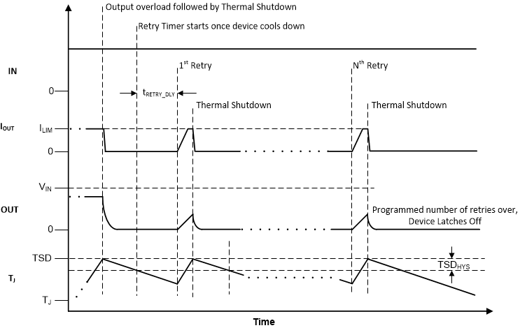
To configure the part for a finite number of auto-retries with a finite auto-retry delay, first choose the capacitor value on RETRY_DLY pin using the following equation.

Next, choose the capacitor value on the NRETRY pin using the following equation.

The number of auto-retries is quantized to certain discrete levels as shown in Table 8-4 .
| NRETRY Calculated From Equation 9 | NRETRY Actual |
|---|---|
| 0 < N < 4 | 4 |
| 4 < N < 16 | 16 |
| 16 < N < 64 | 64 |
| 64 < N < 256 | 256 |
| 256 < N < 1024 | 1024 |
| Auto Retry Delay | 915 ms | 416 ms | 91.7 ms | 9.3 ms | 3 ms |
|---|---|---|---|---|---|
| RETRY_DLY Capacitor | 22 nF | 10 nF | 2.2 nF | 220 pF | 68 pF |
| No. of Auto Retries | NRETRY Capacitor | ||||
| 4 | Open | ||||
| 16 | 47 nF | 22 nF | 4.7 nF | 1 nF | 220 pF |
| 64 | 0.22 μF | 0.1 μF | 22 nF | 2.2 nF | 1 nF |
| 256 | 1 μF | 0.47 μF | 0.1 μF | 10 nF | 4.7 nF |
| 1024 | 3.3 μF | 1.5 μF | 0.47 μF | 33 nF | 10 nF |
| Infinite | Short to GND | ||||
A spreadsheet design tool TPS25980xx Design Calculator is also available for simplified calculations.
 Figure 8-9 Auto-Retry After Fault
The auto-retry logic has a mechanism to reset the count to zero if two consecutive faults occur far apart in time. This ensures that the auto-retry response to any later fault is handled as a fresh sequence and not as a continuation of the previous fault. If the fault which triggered the shutdown and subsequent auto-retry cycle is cleared eventually and does not occur again for a duration equal to 7 retry delay timer periods starting from the last fault, the auto-retry logic resets the internal auto-retry count to zero.