SLVSBM1H June   2013  – November 2016 TPS65132

UNLESS OTHERWISE NOTED, this document contains PRODUCTION DATA.  

  1. Features
  2. Applications
  3. Description
  4. Revision History
  5. Device Comparison Table
  6. Pin Configuration and Functions
  7. Specifications
    1. 7.1 Absolute Maximum Ratings
    2. 7.2 ESD Ratings
    3. 7.3 Recommended Operating Conditions
    4. 7.4 Thermal Information
    5. 7.5 Electrical Characteristics
    6. 7.6 I2C Interface Timing Requirements / Characteristics
    7. 7.7 Typical Characteristics
  8. Detailed Description
    1. 8.1 Overview
    2. 8.2 Functional Block Diagram
    3. 8.3 Feature Description
      1. 8.3.1 Undervoltage Lockout (UVLO)
      2. 8.3.2 Active Discharge
      3. 8.3.3 Boost Converter
        1. 8.3.3.1 Boost Converter Operation
        2. 8.3.3.2 Power-Up And Soft-Start (Boost Converter)
        3. 8.3.3.3 Power-Down (Boost Converter)
        4. 8.3.3.4 Isolation (Boost Converter)
        5. 8.3.3.5 Output Voltage (Boost Converter)
        6. 8.3.3.6 Advanced Power-Save Mode For Light-Load Efficiency And PFM
      4. 8.3.4 LDO Regulator
        1. 8.3.4.1 LDO Operation
        2. 8.3.4.2 Power-Up And Soft-Start (LDO)
        3. 8.3.4.3 Power-Down And Discharge (LDO)
        4. 8.3.4.4 Isolation (LDO)
        5. 8.3.4.5 Setting The Output Voltage (LDO)
      5. 8.3.5 Negative Charge Pump
        1. 8.3.5.1 Operation
        2. 8.3.5.2 Power-Up And Soft-Start (CPN)
        3. 8.3.5.3 Power-Down And Discharge (CPN)
        4. 8.3.5.4 Isolation (CPN)
        5. 8.3.5.5 Setting The Output Voltage (CPN)
    4. 8.4 Device Functional Modes
      1. 8.4.1 Enabling and Disabling the Device
    5. 8.5 Programming
      1. 8.5.1 I2C Serial Interface Description
      2. 8.5.2 I2C Interface Protocol
    6. 8.6 Register Maps
      1. 8.6.1 Registers
        1. 8.6.1.1 VPOS Register - Address: 0x00
        2. 8.6.1.2 VNEG Register - Address 0x01
        3. 8.6.1.3 DLYx Register - Address 0x02 (Only valid for TPS65132Sx)
        4. 8.6.1.4 APPS - SEQU - SEQD - DISP - DISN Register - Address 0x03
        5. 8.6.1.5 Control Register - Address 0xFF
      2. 8.6.2 Factory Default Register Value
  9. Application and Implementation
    1. 9.1 Application Information
    2. 9.2 Typical Applications
      1. 9.2.1 Low-current Applications (≤ 40 mA)
        1. 9.2.1.1 Design Requirements
        2. 9.2.1.2 Detailed Design Procedure
          1. 9.2.1.2.1 Sequencing
          2. 9.2.1.2.2 Boost Converter Design Procedure
            1. 9.2.1.2.2.1 Inductor Selection (Boost Converter)
            2. 9.2.1.2.2.2 Input Capacitor Selection (Boost Converter)
            3. 9.2.1.2.2.3 Output Capacitor Selection (Boost Converter)
          3. 9.2.1.2.3 Input Capacitor Selection (LDO)
          4. 9.2.1.2.4 Output Capacitor Selection (LDO)
          5. 9.2.1.2.5 Input Capacitor Selection (CPN)
          6. 9.2.1.2.6 Output Capacitor Selection (CPN)
          7. 9.2.1.2.7 Flying Capacitor Selection (CPN)
        3. 9.2.1.3 Application Curves
      2. 9.2.2 Mid-current Applications (≤ 80 mA)
        1. 9.2.2.1 Design Requirements
        2. 9.2.2.2 Detailed Design Procedure
          1. 9.2.2.2.1 Boost Converter Design Procedure
            1. 9.2.2.2.1.1 Inductor Selection (Boost Converter)
            2. 9.2.2.2.1.2 Input Capacitor Selection (Boost Converter)
            3. 9.2.2.2.1.3 Output Capacitor Selection (Boost Converter)
          2. 9.2.2.2.2 Input Capacitor Selection (LDO)
          3. 9.2.2.2.3 Output Capacitor Selection (LDO)
          4. 9.2.2.2.4 Input Capacitor Selection (CPN)
          5. 9.2.2.2.5 Output Capacitor Selection (CPN)
          6. 9.2.2.2.6 Flying Capacitor Selection (CPN)
        3. 9.2.2.3 Application Curves
      3. 9.2.3 High-current Applications (≤ 150 mA)
        1. 9.2.3.1 Design Requirements
        2. 9.2.3.2 Detailed Design Procedure
          1. 9.2.3.2.1 Sequencing
          2. 9.2.3.2.2 SYNC = HIGH
          3. 9.2.3.2.3 Startup
        3. 9.2.3.3 Application Curves
  10. 10Power Supply Recommendations
  11. 11Layout
    1. 11.1 Layout Guidelines
    2. 11.2 Layout Example
  12. 12Device and Documentation Support
    1. 12.1 Device Support
      1. 12.1.1 Third-Party Products Disclaimer
    2. 12.2 Receiving Notification of Documentation Updates
    3. 12.3 Community Resources
    4. 12.4 Trademarks
    5. 12.5 Electrostatic Discharge Caution
    6. 12.6 Glossary
  13. 13Mechanical, Packaging, and Orderable Information
    1. 13.1 CSP Package Summary
      1. 13.1.1 Chip Scale Package Dimensions
      2. 13.1.2 RVC Package Summary

Package Options

Mechanical Data (Package|Pins)
Thermal pad, mechanical data (Package|Pins)
Orderable Information

Mechanical, Packaging, and Orderable Information

The following pages include mechanical packaging and orderable information. This information is the most current data available for the designated devices. This data is subject to change without notice and revision of this document. For browser-based versions of this data sheet, refer to the left-hand navigation.

CSP Package Summary

TPS65132 pckg_info_slvsbm1.gif

Chip Scale Package Dimensions

The TPS65132 device is available in a 15-bump chip scale package (YFF, NanoFree™). The package dimensions are given as:

• D = 2108 ±30 μm

• E = 1514 ±30 μm

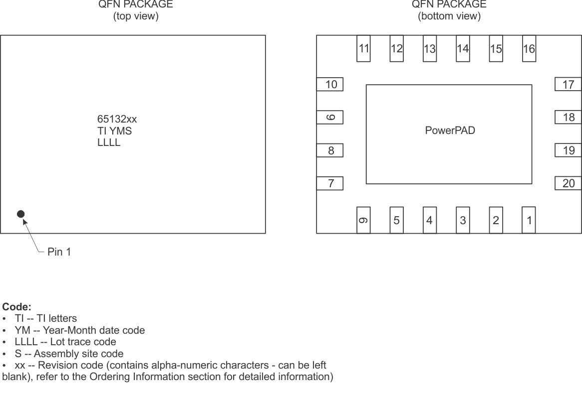
RVC Package Summary

TPS65132 pckg_info_RVC_slvsbm1.gif