JAJSDP7 August 2017 AM5718-HIREL
PRODUCTION DATA.
- 1 デバイスの概要
- 2 改訂履歴
- 3 Device Comparison
-
4 Terminal Configuration and Functions
- 4.1 Terminal Assignment
- 4.2 Ball Characteristics
- 4.3 Multiplexing Characteristics
- 4.4
Signal Descriptions
- 4.4.1 Video Input Ports (VIP)
- 4.4.2 Display Subsystem - Video Output Ports
- 4.4.3 Display Subsystem - High-Definition Multimedia Interface (HDMI)
- 4.4.4 Camera Serial Interface 2 CAL bridge (CSI2)
- 4.4.5 External Memory Interface (EMIF)
- 4.4.6 General-Purpose Memory Controller (GPMC)
- 4.4.7 Timers
- 4.4.8 Inter-Integrated Circuit Interface (I2C)
- 4.4.9 HDQ / 1-Wire Interface (HDQ1W)
- 4.4.10 Universal Asynchronous Receiver Transmitter (UART)
- 4.4.11 Multichannel Serial Peripheral Interface (McSPI)
- 4.4.12 Quad Serial Peripheral Interface (QSPI)
- 4.4.13 Multichannel Audio Serial Port (McASP)
- 4.4.14 Universal Serial Bus (USB)
- 4.4.15 SATA
- 4.4.16 Peripheral Component Interconnect Express (PCIe)
- 4.4.17 Controller Area Network Interface (DCAN)
- 4.4.18 Ethernet Interface (GMAC_SW)
- 4.4.19 Media Local Bus (MLB) Interface
- 4.4.20 eMMC/SD/SDIO
- 4.4.21 General-Purpose Interface (GPIO)
- 4.4.22 Keyboard controller (KBD)
- 4.4.23 Pulse Width Modulation (PWM) Interface
- 4.4.24 Programmable Real-Time Unit Subsystem and Industrial Communication Subsystem (PRU-ICSS)
- 4.4.25 Test Interfaces
- 4.4.26 System and Miscellaneous
- 4.4.27 Power Supplies
-
5 Specifications
- 5.1 Absolute Maximum Ratings
- 5.2 ESD Ratings
- 5.3 Power On Hours (POH) Limits
- 5.4 Recommended Operating Conditions
- 5.5 Operating Performance Points
- 5.6 Power Consumption Summary
- 5.7
Electrical Characteristics
- 5.7.1 LVCMOS DDR DC Electrical Characteristics
- 5.7.2 HDMIPHY DC Electrical Characteristics
- 5.7.3 Dual Voltage LVCMOS I2C DC Electrical Characteristics
- 5.7.4 IQ1833 Buffers DC Electrical Characteristics
- 5.7.5 IHHV1833 Buffers DC Electrical Characteristics
- 5.7.6 LVCMOS OSC Buffers DC Electrical Characteristics
- 5.7.7 LVCMOS CSI2 DC Electrical Characteristics
- 5.7.8 BMLB18 Buffers DC Electrical Characteristics
- 5.7.9 BC1833IHHV Buffers DC Electrical Characteristics
- 5.7.10 USBPHY DC Electrical Characteristics
- 5.7.11 Dual Voltage SDIO1833 DC Electrical Characteristics
- 5.7.12 Dual Voltage LVCMOS DC Electrical Characteristics
- 5.7.13 SATAPHY DC Electrical Characteristics
- 5.7.14 SERDES DC Electrical Characteristics
- 5.8 Thermal Characteristics
- 5.9 Power Supply Sequences
- 6 Clock Specifications
-
7 Timing Requirements and Switching Characteristics
- 7.1 Timing Test Conditions
- 7.2 Interface Clock Specifications
- 7.3 Timing Parameters and Information
- 7.4 Recommended Clock and Control Signal Transition Behavior
- 7.5 Virtual and Manual I/O Timing Modes
- 7.6 Video Input Ports (VIP)
- 7.7 Display Subsystem - Video Output Ports
- 7.8 Display Subsystem - High-Definition Multimedia Interface (HDMI)
- 7.9 Camera Serial Interface 2 CAL bridge (CSI2)
- 7.10 External Memory Interface (EMIF)
- 7.11 General-Purpose Memory Controller (GPMC)
- 7.12 Timers
- 7.13 Inter-Integrated Circuit Interface (I2C)
- 7.14 HDQ / 1-Wire Interface (HDQ1W)
- 7.15 Universal Asynchronous Receiver Transmitter (UART)
- 7.16 Multichannel Serial Peripheral Interface (McSPI)
- 7.17 Quad Serial Peripheral Interface (QSPI)
- 7.18 Multichannel Audio Serial Port (McASP)
- 7.19 Universal Serial Bus (USB)
- 7.20 Serial Advanced Technology Attachment (SATA)
- 7.21 Peripheral Component Interconnect Express (PCIe)
- 7.22 Controller Area Network Interface (DCAN)
- 7.23 Ethernet Interface (GMAC_SW)
- 7.24
eMMC/SD/SDIO
- 7.24.1
MMC1-SD Card Interface
- 7.24.1.1 Default speed, 4-bit data, SDR, half-cycle
- 7.24.1.2 High speed, 4-bit data, SDR, half-cycle
- 7.24.1.3 SDR12, 4-bit data, half-cycle
- 7.24.1.4 SDR25, 4-bit data, half-cycle
- 7.24.1.5 UHS-I SDR50, 4-bit data, half-cycle
- 7.24.1.6 UHS-I SDR104, 4-bit data, half-cycle
- 7.24.1.7 UHS-I DDR50, 4-bit data
- 7.24.2 MMC2 - eMMC
- 7.24.3 MMC3 and MMC4-SDIO/SD
- 7.24.1
MMC1-SD Card Interface
- 7.25 General-Purpose Interface (GPIO)
- 7.26 PRU-ICSS Interfaces
- 7.27 System and Miscellaneous interfaces
- 7.28 Test Interfaces
-
8 Applications, Implementation, and Layout
- 8.1 Power Supply Mapping
- 8.2
DDR3 Board Design and Layout Guidelines
- 8.2.1 DDR3 General Board Layout Guidelines
- 8.2.2
DDR3 Board Design and Layout Guidelines
- 8.2.2.1 Board Designs
- 8.2.2.2 DDR3 EMIF
- 8.2.2.3 DDR3 Device Combinations
- 8.2.2.4 DDR3 Interface Schematic
- 8.2.2.5 Compatible JEDEC DDR3 Devices
- 8.2.2.6 PCB Stackup
- 8.2.2.7 Placement
- 8.2.2.8 DDR3 Keepout Region
- 8.2.2.9 Bulk Bypass Capacitors
- 8.2.2.10 High-Speed Bypass Capacitors
- 8.2.2.11 Net Classes
- 8.2.2.12 DDR3 Signal Termination
- 8.2.2.13 VREF_DDR Routing
- 8.2.2.14 VTT
- 8.2.2.15 CK and ADDR_CTRL Topologies and Routing Definition
- 8.2.2.16 Data Topologies and Routing Definition
- 8.2.2.17 Routing Specification
- 8.3 High Speed Differential Signal Routing Guidance
- 8.4 Power Distribution Network Implementation Guidance
- 8.5 Single-Ended Interfaces
- 8.6 Clock Routing Guidelines
- 9 デバイスおよびドキュメントのサポート
- 10メカニカル、パッケージ、および注文情報
1 デバイスの概要
1.1 特長
- シリコン・リビジョン1.0の情報については、SPRS919を参照
- ARM® Cortex®-A15マイクロプロセッサ・サブシステム
- C66x浮動小数点VLIW DSP
- C67xおよびC64x+と完全にオブジェクト・コード互換
- サイクルごとに最高32回の16×16ビット固定小数点乗算
- 最大512KBのオンチップL3 RAM
- レベル3 (L3)とレベル4 (L4)の相互接続
- DDR3/DDR3Lメモリ・インターフェイス(EMIF)モジュール
- DDR3-1333 (667MHz)までをサポート
- 単一チップ・セレクトで最大2GB
- デュアルARM® Cortex®-M4コプロセッサ
- IVA-HDサブシステム
- ディスプレイ・サブシステム
- フルHDビデオ(1920×1080p、60fps)
- 複数のビデオ入力とビデオ出力
- 2Dおよび3Dグラフィックス
- DMAエンジンを搭載し、最大3つのパイプラインを持つディスプレイ・コントローラ
- HDMI™エンコーダ: HDMI 1.4aおよびDVI 1.0準拠
- 2x デュアルコアのプログラマブルなリアルタイム・ユニットと産業用通信サブシステム(PRU-ICSS)
- アクセラレータ(BB2D)サブシステム
- Vivante™ GC320コア
- ビデオ・プロセッシング・エンジン(VPE)
- シングル・コアのPowerVR® SGX544 3D GPUを利用可能
- 1つのビデオ入力ポート(VIP)モジュール
- 最大4つの多重化された入力ポートをサポート
- 汎用メモリ・コントローラ(GPMC)
- 拡張ダイレクト・メモリ・アクセス(EDMA)コントローラ
- イーサネット・サブシステム
- 16個の32ビット汎用タイマ
- 32ビットMPUウォッチドッグ・タイマ
- 5つのI2C (Inter-Integrated Circuit)ポート
- HDQ™/1-Wire®インターフェイス
- 10個の構成可能なUART/IrDA/CIRモジュール
- 4つのマルチチャネル・シリアル・ペリフェラル・インターフェイス(McSPI)
- クワッドSPIインターフェイス(QSPI)
- SATA Gen2インターフェイス
- 8つのマルチチャネル・オーディオ・シリアル・ポート(McASP)モジュール
- SuperSpeed USB 3.0デュアル・ロール・デバイス
- High-Speed USB 2.0デュアル・ロール・デバイス
- 4つのマルチメディア・カード/セキュア・デジタル/セキュア・デジタル入出力インターフェイス(MMC/SD/SDIO)
- 2本の5Gbpsレーンを持つPCI Express® 3.0サブシステム
- 1つの2レーン、Gen2準拠のポート
- または2つの1レーン、Gen2準拠のポート
- デュアル・コントローラ・エリア・ネットワーク(DCAN)モジュール
- CAN 2.0Bプロトコル
- MIPI® CSI-2カメラ・シリアル・インターフェイス
- 最大215の汎用I/O (GPIO)ピン
- 電源、リセット、クロック管理
- CToolsテクノロジによるオンチップ・デバッグ
- 28nm CMOSテクノロジ
- 23mm×23mm、0.8mmピッチ、760ピンBGA (ZBO)
1.2 アプリケーション
- 産業用通信
- ヒューマン・マシン・インターフェイス(HMI)
- オートメーションおよび制御
- 高性能アプリケーション
- その他の汎用
1.3 概要
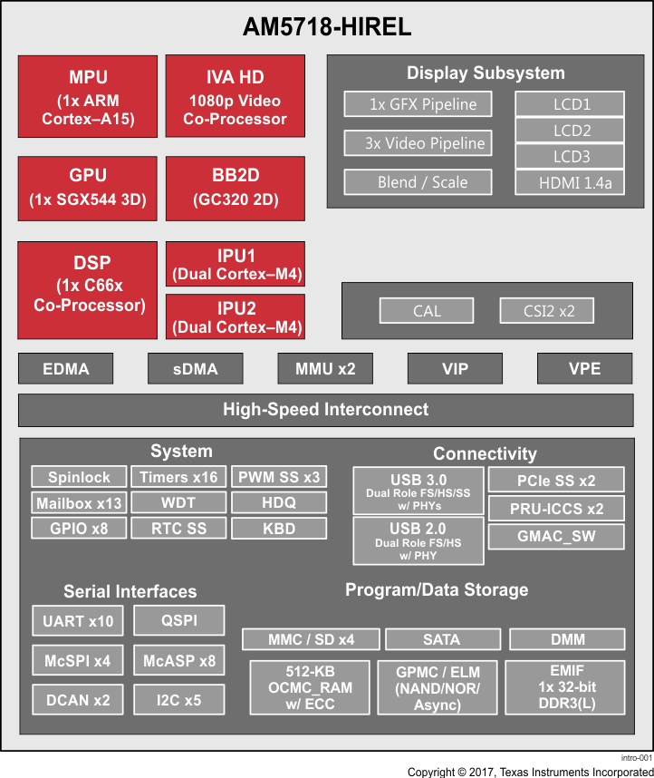
AM5718-HIREL Sitara ARMアプリケーション・プロセッサは、今日の組み込み製品に求められる高度な処理の要求を満たすため開発された製品です。
AM5718-HIRELデバイスは、完全に統合された混在プロセッサ・ソリューションの最高の柔軟性により、高い処理性能を実現します。このデバイスには、プログラム可能なビデオ処理と、高度に統合されたペリフェラル・セットも組み込まれています。
Neon™拡張機能を搭載したシングル・コアのARM Cortex-A15 RISC CPUと、TI C66x VLIW浮動小数点DSPコアにより、プログラムが可能です。ARMプロセッサにより、開発者は制御機能と、DSPおよびコプロセッサ上でプログラムされるビジョン・アルゴリズムとを分離して、システム・ソフトウェアの複雑性を低減できます。
さらに、TIはARMおよびC66x DSP用に完全な開発ツールのセットを提供しており、Cコンパイラ、DSPアセンブリ・オプティマイザなどを使用してプログラミングとスケジューリングを簡素化し、デバッグ・インターフェイスによってソースコードの実行を見通すことができます。
AM5718-HIREL Sitara ARMプロセッサ・ファミリは、AEC-Q100標準に従って認定済みです。
製品情報
| 型番 | パッケージ | 本体サイズ |
|---|---|---|
| AM5718-HIREL | FCBGA (760) | 23.00mm×23.00mm |
