SLPS393A October 2013 – January 2015 CSD17571Q2
PRODUCTION DATA.
- 1Features
- 2Applications
- 3Description
- 4Revision History
- 5 Specifications
- 6Device and Documentation Support
- 7Mechanical, Packaging, and Orderable Information
パッケージ・オプション
デバイスごとのパッケージ図は、PDF版データシートをご参照ください。
メカニカル・データ(パッケージ|ピン)
- DQK|6
サーマルパッド・メカニカル・データ
発注情報
7 Mechanical, Packaging, and Orderable Information
The following pages include mechanical, packaging, and orderable information. This information is the most current data available for the designated devices. This data is subject to change without notice and revision of this document. For browser-based versions of this data sheet, refer to the left-hand navigation.
7.1 Q2 Package Dimensions
| DIM | MILLIMETERS | INCHES | ||||
|---|---|---|---|---|---|---|
| MIN | NOM | MAX | MIN | NOM | MAX | |
| A | 0.700 | 0.750 | 0.800 | 0.028 | 0.030 | 0.032 |
| A1 | 0.000 | 0.050 | 0.000 | 0.002 | ||
| b | 0.250 | 0.300 | 0.350 | 0.010 | 0.012 | 0.014 |
| C | 0.203 TYP | 0.008 TYP | ||||
| D | 2.000 TYP | 0.080 TYP | ||||
| D1 | 0.900 | 0.950 | 1.000 | 0.036 | 0.038 | 0.040 |
| D2 | 0.300 TYP | 0.012 TYP | ||||
| E | 2.000 TYP | 0.080 TYP | ||||
| E1 | 0.900 | 1.000 | 1.100 | 0.036 | 0.040 | 0.044 |
| E2 | 0.280 TYP | 0.0112 TYP | ||||
| E3 | 0.470 TYP | 0.0188 TYP | ||||
| e | 0.650 BSC | 0.026 TYP | ||||
| K | 0.280 TYP | 0.0112 TYP | ||||
| K1 | 0.350 TYP | 0.014 TYP | ||||
| K2 | 0.200 TYP | 0.008 TYP | ||||
| K3 | 0.200 TYP | 0.008 TYP | ||||
| K4 | 0.470 TYP | 0.0188 TYP | ||||
| L | 0.200 | 0.25 | 0.300 | 0.008 | 0.010 | 0.012 |
7.1.1 Recommended PCB Pattern
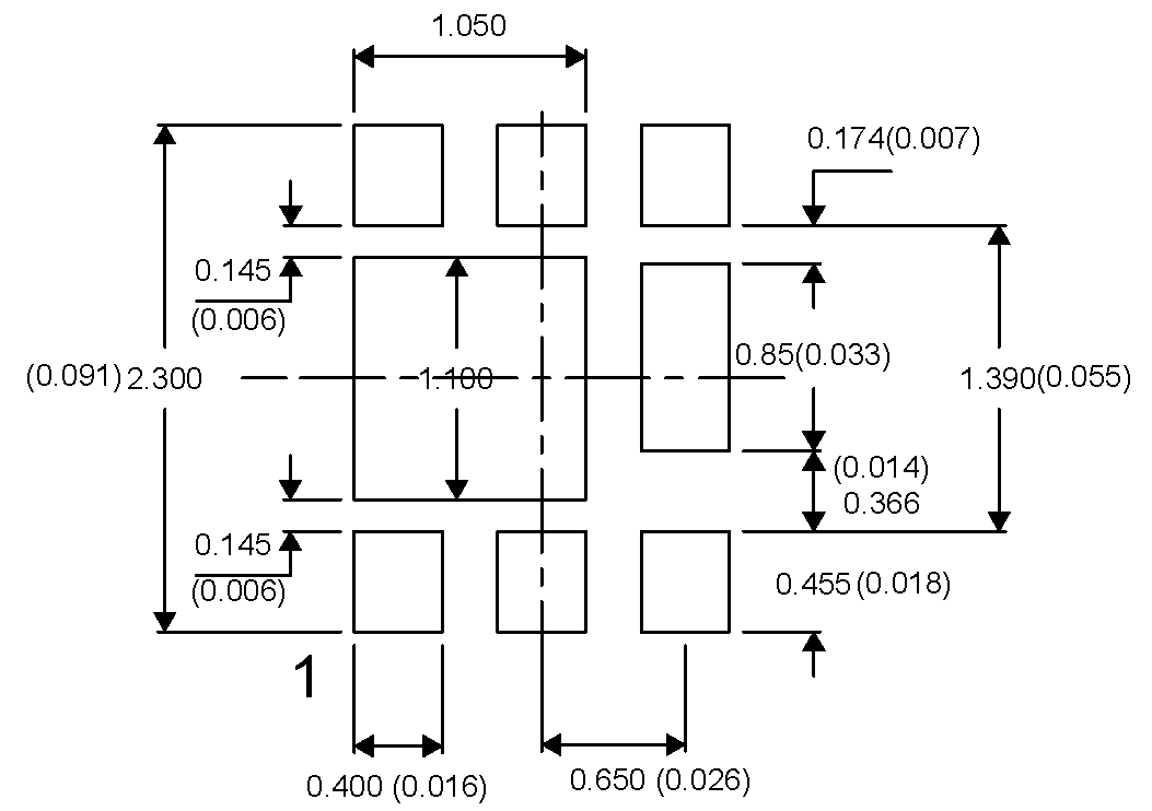
For recommended circuit layout for PCB designs, see application note SLPA005 – Reducing Ringing Through PCB Layout Techniques.
7.1.2 Recommended Stencil Pattern
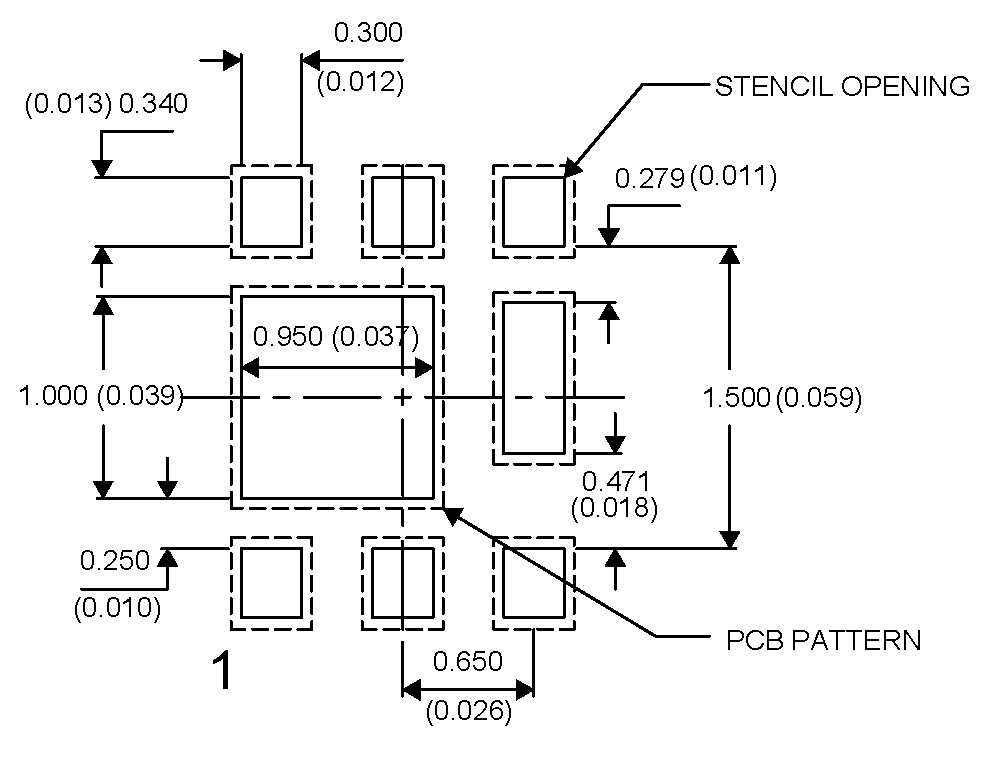
NOTE:
All dimensions are in mm, unless otherwise specified.7.2 Q2 Tape and Reel Information
NOTES:
1. Measured from centerline of sprocket hole to centerline of pocket2. Cumulative tolerance of 10 sprocket holes is ±0.20
3. Other material available
4. Typical SR of form tape Max 109 OHM/SQ
5. All dimensions are in mm, unless otherwise specified.