SLPS320B November 2012 – May 2017 CSD18502Q5B
PRODUCTION DATA.
- 1Features
- 2Applications
- 3Description
- 4Revision History
- 5Specifications
- 6Device and Documentation Support
- 7Mechanical, Packaging, and Orderable Information
パッケージ・オプション
デバイスごとのパッケージ図は、PDF版データシートをご参照ください。
メカニカル・データ(パッケージ|ピン)
- DNK|8
サーマルパッド・メカニカル・データ
発注情報
7 Mechanical, Packaging, and Orderable Information
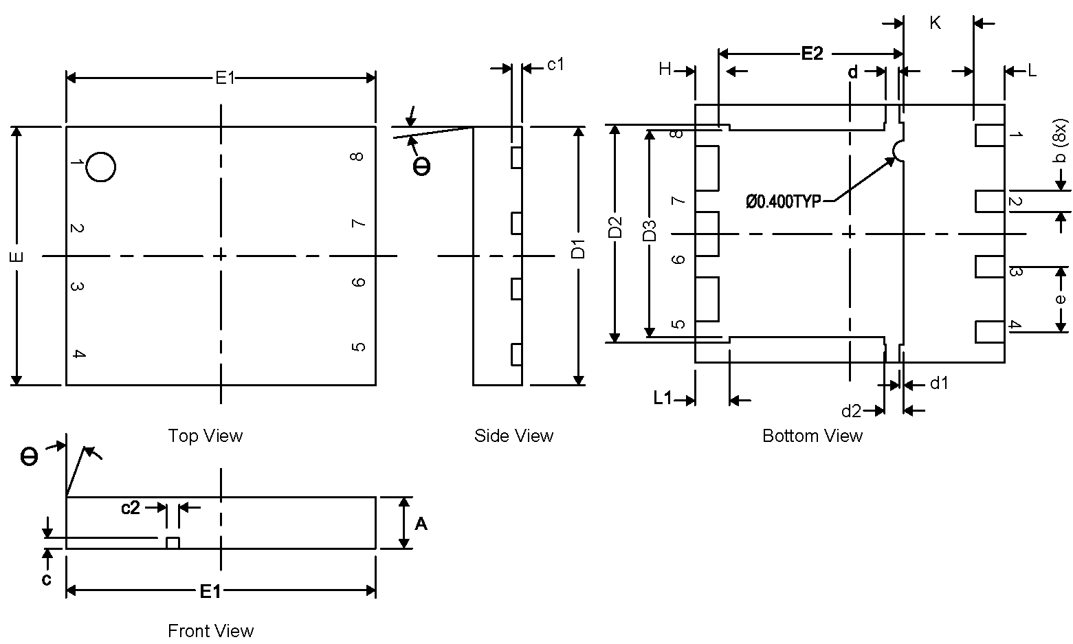
7.1 Q5B Package Dimensions
| DIM | MILLIMETERS | ||
|---|---|---|---|
| MIN | NOM | MAX | |
| A | 0.95 | 1.00 | 1.05 |
| b | 0.36 | 0.41 | 0.46 |
| c | 0.15 | 0.20 | 0.25 |
| c1 | 0.15 | 0.20 | 0.25 |
| c2 | 0.20 | 0.25 | 0.30 |
| D1 | 4.90 | 5.00 | 5.10 |
| D2 | 4.12 | 4.22 | 4.32 |
| d | 0.20 | 0.25 | 0.30 |
| E | 4.90 | 5.00 | 5.10 |
| E1 | 5.90 | 6.00 | 6.10 |
| E2 | 3.48 | 3.58 | 3.68 |
| e | 1.27 TYP | ||
| L | 0.46 | 0.56 | 0.66 |
| θ | 0° | — | — |
| K | 1.40 TYP | ||
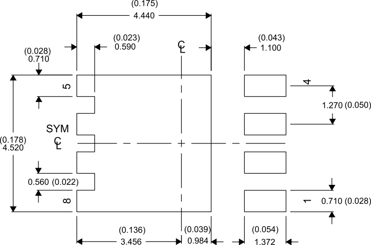
7.2 Recommended PCB Pattern

For recommended circuit layout for PCB designs, see Reducing Ringing Through PCB Layout Techniques (SLPA005).
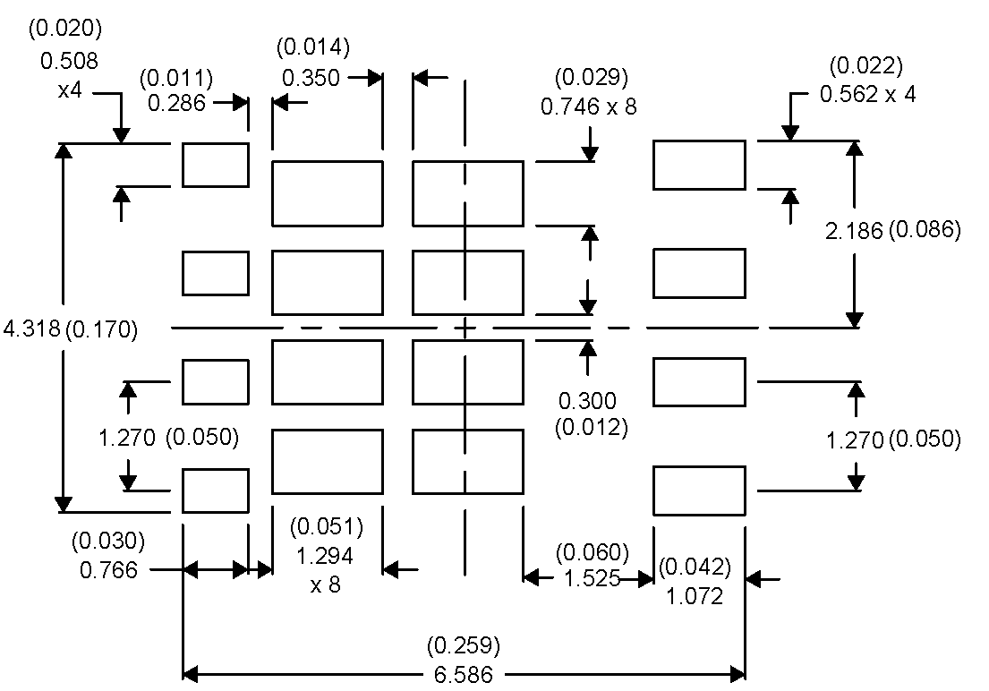
7.3 Recommended Stencil Pattern

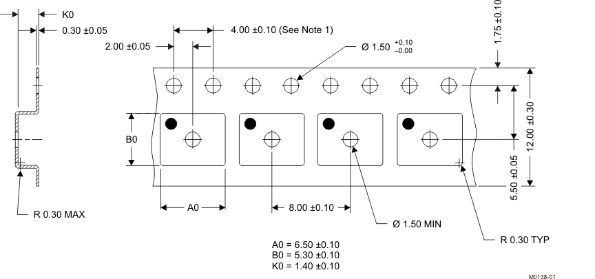
7.4 Q5B Tape and Reel Information

Notes:
- 10-sprocket hole-pitch cumulative tolerance ±0.2
- Camber not to exceed 1 mm in 100 mm, noncumulative over 250 mm
- Material: black static-dissipative polystyrene
- All dimensions are in mm (unless otherwise specified)
- A0 and B0 measured on a plane 0.3 mm above the bottom of the pocket
