JAJSEF2D June   2013  – December 2021 DAC7760 , DAC8760

PRODUCTION DATA  

  1. 特長
  2. アプリケーション
  3. 概要
  4. Revision History
  5. Device Comparison Table
  6. Pin Configuration and Functions
  7. Specifications
    1. 7.1  Absolute Maximum Ratings
    2. 7.2  ESD Ratings
    3. 7.3  Recommended Operating Conditions
    4. 7.4  Thermal Information
    5. 7.5  Electrical Characteristics
    6. 7.6  Electrical Characteristics: AC
    7. 7.7  Timing Requirements: Write Mode
    8. 7.8  Timing Requirements: Readback Mode
    9. 7.9  Timing Diagrams
    10. 7.10 Typical Characteristics
  8. Detailed Description
    1. 8.1 Overview
    2. 8.2 Functional Block Diagram
    3. 8.3 Feature Description
      1. 8.3.1  DAC Architecture
      2. 8.3.2  Voltage Output Stage
      3. 8.3.3  Current Output Stage
      4. 8.3.4  Internal Reference
      5. 8.3.5  Digital Power Supply
      6. 8.3.6  DAC Clear
      7. 8.3.7  Power-On Reset
      8. 8.3.8  Alarm Detection
      9. 8.3.9  Watchdog Timer
      10. 8.3.10 Frame Error Checking
      11. 8.3.11 User Calibration
      12. 8.3.12 Programmable Slew Rate
    4. 8.4 Device Functional Modes
      1. 8.4.1 Setting Voltage and Current Output Ranges
      2. 8.4.2 Boost Configuration for IOUT
      3. 8.4.3 Filtering the Current Output (only on the VQFN package)
      4. 8.4.4 HART Interface
        1. 8.4.4.1 For 4-mA to 20-mA Mode
        2. 8.4.4.2 For All Current Output Modes
    5. 8.5 Programming
      1. 8.5.1 Serial Peripheral Interface (SPI)
        1. 8.5.1.1 SPI Shift Register
        2. 8.5.1.2 Write Operation
        3. 8.5.1.3 Read Operation
        4. 8.5.1.4 Stand-Alone Operation
        5. 8.5.1.5 Multiple Devices on the Bus
    6. 8.6 Register Maps
      1. 8.6.1 DACx760 Command and Register Map
        1. 8.6.1.1 DACx760 Register Descriptions
          1. 8.6.1.1.1 Control Register
          2. 8.6.1.1.2 Configuration Register
          3. 8.6.1.1.3 DAC Registers
          4. 8.6.1.1.4 Reset Register
          5. 8.6.1.1.5 Status Register
  9. Application and Implementation
    1. 9.1 Application Information
      1. 9.1.1 Controlling the VOUT and IOUT Pins
        1. 9.1.1.1 VOUT and IOUT Pins are Independent Outputs, Never Simultaneously Enabled
        2. 9.1.1.2 VOUT and IOUT Pins are Independent Outputs, Simultaneously Enabled
        3. 9.1.1.3 VOUT and IOUT Pins are Tied Together, Never Simultaneously Enabled
      2. 9.1.2 Implementing HART in All Current Output Modes
        1. 9.1.2.1 Using CAP2 Pin on VQFN Package
        2. 9.1.2.2 Using the ISET-R Pin
      3. 9.1.3 Short-Circuit Current Limiting
    2. 9.2 Typical Application
      1. 9.2.1 Design Requirements
      2. 9.2.2 Detailed Design Procedure
      3. 9.2.3 Application Curves
  10. 10Power Supply Recommendations
  11. 11Layout
    1. 11.1 Layout Guidelines
      1. 11.1.1 Thermal Considerations
    2. 11.2 Layout Example
  12. 12Device and Documentation Support
    1. 12.1 Documentation Support
      1. 12.1.1 Related Documentation
    2. 12.2 Receiving Notification of Documentation Updates
    3. 12.3 サポート・リソース
    4. 12.4 Trademarks
    5. 12.5 Electrostatic Discharge Caution
    6. 12.6 Glossary
  13. 13Mechanical, Packaging, and Orderable Information

パッケージ・オプション

メカニカル・データ(パッケージ|ピン)
サーマルパッド・メカニカル・データ
発注情報

概要

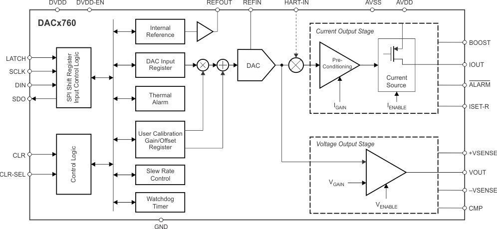
DACx760 は、高精度の完全統合型 12ビット および 16 ビットの D/A コンバータ (DAC) で、産業用プロセス制御アプリケーションの要件を満たすよう設計されています。これらのデバイスは、4 mA~20mA、0mA~20mA、0mA~24 mAの電流出力、または、0V~5V、0V~10V、±5V、±10V、もしくは 10% のオーバーレンジ (0V~5.5V、0V~11V、±5.5V、±11V) の電圧出力にプログラムできます。電流と電圧の出力はどちらも同時に有効にでき、単一のデータ・レジスタで制御されます。

これらのデバイスは、パワーオン・リセット機能を備えており、電源オン時には既知の状態 (IOUT と VOUT はどちらもディセーブルで Hi-Z 状態) になります。CLR および CLR-SEL ピンは、電圧出力をゼロスケールまたは中間スケールに設定し、電流出力が有効な場合は範囲の下限に設定します。ゼロ・レジスタおよびゲイン・レジスタをプログラムして、最終システムの中でデバイスをデジタル的に較正できます。出力のスルー・レートも、レジスタによりプログラム可能です。電流出力に外部の HART® 信号を重ね合わせることができます。これらのデバイスは、単一の 10V~36V 電源または最大 ±18V のデュアル電源で動作します。

製品情報
部品番号 パッケージ(1) 本体サイズ (公称)
DACx760 HTSSOP (24) 7.80mm × 4.40mm
VQFN (40) 6.00mm × 6.00mm
提供されているすべてのパッケージについては、データシートの末尾にあるパッケージ・オプションについての付録を参照してください。
GUID-20211207-SS0I-ZWGJ-G5HK-DBKZCQMQNH3C-low.gif ブロック図