JAJSGY9C february   2019  – july 2023 DLP2010

PRODUCTION DATA  

  1.   1
  2. 特長
  3. アプリケーション
  4. 概要
  5. Revision History
  6. Pin Configuration and Functions
  7. Specifications
    1. 6.1  Absolute Maximum Ratings
    2. 6.2  Storage Conditions
    3. 6.3  ESD Ratings
    4. 6.4  Recommended Operating Conditions
    5. 6.5  Thermal Information
    6. 6.6  Electrical Characteristics
    7. 6.7  Timing Requirements
    8. 6.8  Switching Characteristics
    9. 6.9  System Mounting Interface Loads
    10. 6.10 Physical Characteristics of the Micromirror Array
    11. 6.11 Micromirror Array Optical Characteristics
    12. 6.12 Window Characteristics
    13. 6.13 Chipset Component Usage Specification
    14. 6.14 Software Requirements
  8. Detailed Description
    1. 7.1 Overview
    2. 7.2 Functional Block Diagram
    3. 7.3 Feature Description
      1. 7.3.1 Power Interface
      2. 7.3.2 Low-Speed Interface
      3. 7.3.3 High-Speed Interface
      4. 7.3.4 Timing
    4. 7.4 Device Functional Modes
    5. 7.5 Optical Interface and System Image Quality Considerations
      1. 7.5.1 Optical Interface and System Image Quality
        1. 7.5.1.1 Numerical Aperture and Stray Light Control
        2. 7.5.1.2 Pupil Match
        3. 7.5.1.3 Illumination Overfill
    6. 7.6 Micromirror Array Temperature Calculation
    7. 7.7 Micromirror Power Density Calculation
    8. 7.8 Micromirror Landed-On/Landed-Off Duty Cycle
      1. 7.8.1 Definition of Micromirror Landed-On and Landed-Off Duty Cycle
      2. 7.8.2 Landed Duty Cycle and Useful Life of the DMD
      3. 7.8.3 Landed Duty Cycle and Operational DMD Temperature
      4. 7.8.4 Estimating the Long-Term Average Landed Duty Cycle of a Product or Application
  9. Application and Implementation
    1. 8.1 Application Information
    2. 8.2 Typical Application
      1. 8.2.1 Design Requirements
      2. 8.2.2 Detailed Design Procedure
      3. 8.2.3 Application Curve
  10. Power Supply Recommendations
    1. 9.1 DMD Power Supply Power-Up Procedure
    2. 9.2 DMD Power Supply Power-Down Procedure
    3. 9.3 Power Supply Sequencing Requirements
  11. 10Layout
    1. 10.1 Layout Guidelines
    2. 10.2 Layout Example
  12. 11Device and Documentation Support
    1. 11.1 Device Support
      1. 11.1.1 サード・パーティ製品に関する免責事項
      2. 11.1.2 Device Nomenclature
      3. 11.1.3 Device Markings
    2. 11.2 Related Links
    3. 11.3 ドキュメントの更新通知を受け取る方法
    4. 11.4 サポート・リソース
    5. 11.5 Trademarks
    6. 11.6 静電気放電に関する注意事項
    7. 11.7 用語集
  13. 12Mechanical, Packaging, and Orderable Information

パッケージ・オプション

メカニカル・データ(パッケージ|ピン)
サーマルパッド・メカニカル・データ
発注情報

概要

DLP2010 デジタル・マイクロミラー・デバイス (DMD) は、デジタル制御の MOEMS (micro-opto-electromechanical system) 空間光変調器 (SLM) です。この DMD を適切な光学システムと組み合わせることで、画像、映像、パターンを表示できます。このデバイスは、DLP2010 DMD、DLPC3430 / DLPC3435 コントローラ、DLPA200x / DLPA3000 PMIC/LED ドライバで構成されるチップセットの一部です。この DMD は小型であるため、小さな外形と低消費電力であることが重視される携帯機器に使用できます。小さなパッケージと、LED の小さなサイズが、スペースが制約される光エンジンに理想的です。

製品情報
部品番号 (1) パッケージ 本体サイズ (公称)
DLP2010 FQJ (40) 15.9mm × 5.3mm
利用可能なすべてのパッケージについては、データシートの末尾にある注文情報を参照してください。
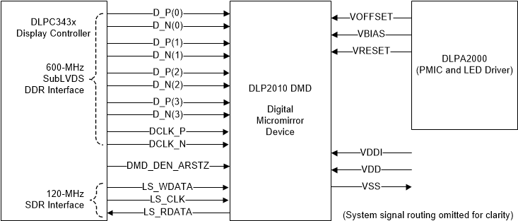
GUID-E2F1CE04-8E67-4E7B-B623-47ED641A6F5D-low.gif0.2 WVGA チップセット