JAJSKV6C August   2020  – August 2022 DRV8714-Q1 , DRV8718-Q1

PRODUCTION DATA  

  1. 特長
  2. アプリケーション
  3. 概要
  4. Revision History
  5. Device Comparison Table
  6. Pin Configuration and Functions
    1. 6.1 VQFN (RVJ) 56-Pin Package and Pin Functions
    2. 6.2 VQFN (RHA) 40-Pin Package and Pin Functions
    3. 6.3 HTQFP (PHP) 48-Pin Package and Pin Functions
  7. Specifications
    1. 7.1 Absolute Maximum Ratings
    2. 7.2 ESD Ratings
    3. 7.3 Recommended Operating Conditions
    4. 7.4 Thermal Information
    5. 7.5 Electrical Characteristics
    6. 7.6 Timing Requirements
    7. 7.7 Timing Diagrams
    8. 7.8 Typical Characteristics
  8. Detailed Description
    1. 8.1 Overview
    2. 8.2 Functional Block Diagram
    3. 8.3 Feature Description
      1. 8.3.1 External Components
      2. 8.3.2 Device Interface Variants
        1. 8.3.2.1 Serial Peripheral Interface (SPI)
        2. 8.3.2.2 Hardware (H/W)
      3. 8.3.3 Input PWM Control Modes
        1. 8.3.3.1 Half-Bridge Control Scheme With Input PWM Mapping
          1. 8.3.3.1.1 DRV8718-Q1 Half-Bridge Control
          2. 8.3.3.1.2 DRV8714-Q1 Half-Bridge Control
        2. 8.3.3.2 H-Bridge Control
          1. 8.3.3.2.1 DRV8714-Q1 H-Bridge Control
        3. 8.3.3.3 Split HS and LS Solenoid Control
          1. 8.3.3.3.1 DRV8714-Q1 Split HS and LS Solenoid Control
      4. 8.3.4 Smart Gate Driver
        1. 8.3.4.1 Functional Block Diagram
        2. 8.3.4.2 Slew Rate Control (IDRIVE)
        3. 8.3.4.3 Gate Drive State Machine (TDRIVE)
        4. 8.3.4.4 Propagation Delay Reduction (PDR)
          1. 8.3.4.4.1 PDR Pre-Charge/Pre-Discharge Control Loop Operation Details
            1. 8.3.4.4.1.1 PDR Pre-Charge/Pre-Discharge Setup
          2. 8.3.4.4.2 PDR Post-Charge/Post-Discharge Control Loop Operation Details
            1. 8.3.4.4.2.1 PDR Post-Charge/Post-Discharge Setup
          3. 8.3.4.4.3 Detecting Drive and Freewheel MOSFET
        5. 8.3.4.5 Automatic Duty Cycle Compensation (DCC)
        6. 8.3.4.6 Closed Loop Slew Time Control (STC)
          1. 8.3.4.6.1 STC Control Loop Setup
      5. 8.3.5 Tripler (Dual-Stage) Charge Pump
      6. 8.3.6 Wide Common-Mode Current Shunt Amplifiers
      7. 8.3.7 Pin Diagrams
        1. 8.3.7.1 Logic Level Input Pin (INx/ENx, INx/PHx, nSLEEP, nSCS, SCLK, SDI)
        2. 8.3.7.2 Logic Level Push Pull Output (SDO)
        3. 8.3.7.3 Logic Level Multi-Function Pin (DRVOFF/nFLT)
        4. 8.3.7.4 Quad-Level Input (GAIN, MODE)
        5. 8.3.7.5 Six-Level Input (IDRIVE, VDS)
      8. 8.3.8 Protection and Diagnostics
        1. 8.3.8.1  Gate Driver Disable (DRVOFF/nFLT and EN_DRV)
        2. 8.3.8.2  Low IQ Powered Off Braking (POB, BRAKE)
        3. 8.3.8.3  Fault Reset (CLR_FLT)
        4. 8.3.8.4  DVDD Logic Supply Power on Reset (DVDD_POR)
        5. 8.3.8.5  PVDD Supply Undervoltage Monitor (PVDD_UV)
        6. 8.3.8.6  PVDD Supply Overvoltage Monitor (PVDD_OV)
        7. 8.3.8.7  VCP Charge Pump Undervoltage Lockout (VCP_UV)
        8. 8.3.8.8  MOSFET VDS Overcurrent Protection (VDS_OCP)
        9. 8.3.8.9  Gate Driver Fault (VGS_GDF)
        10. 8.3.8.10 Thermal Warning (OTW)
        11. 8.3.8.11 Thermal Shutdown (OTSD)
        12. 8.3.8.12 Offline Short Circuit and Open Load Detection (OOL and OSC)
        13. 8.3.8.13 Watchdog Timer
        14. 8.3.8.14 Fault Detection and Response Summary Table
    4. 8.4 Device Functional Modes
      1. 8.4.1 Inactive or Sleep State
      2. 8.4.2 Standby State
      3. 8.4.3 Operating State
    5. 8.5 Programming
      1. 8.5.1 SPI Interface
      2. 8.5.2 SPI Format
      3. 8.5.3 SPI Interface for Multiple Slaves
        1. 8.5.3.1 SPI Interface for Multiple Slaves in Daisy Chain
    6. 8.6 Register Maps
      1. 8.6.1 DRV8718-Q1 Register Map
      2. 8.6.2 DRV8714-Q1 Register Map
      3. 8.6.3 DRV8718-Q1 Register Descriptions
        1. 8.6.3.1 DRV8718-Q1_STATUS Registers
        2. 8.6.3.2 DRV8718-Q1_CONTROL Registers
        3. 8.6.3.3 DRV8718-Q1_CONTROL_ADV Registers
        4. 8.6.3.4 DRV8718-Q1_STATUS_ADV Registers
      4. 8.6.4 DRV8714-Q1 Register Descriptions
        1. 8.6.4.1 DRV8714-Q1_STATUS Registers
        2. 8.6.4.2 DRV8714-Q1_CONTROL Registers
        3. 8.6.4.3 DRV8714-Q1_CONTROL_ADV Registers
        4. 8.6.4.4 DRV8714-Q1_STATUS_ADV Registers
  9. Application Implementation
    1. 9.1 Application Information
    2. 9.2 Typical Application
      1. 9.2.1 Design Requirements
      2. 9.2.2 Detailed Design Procedure
        1. 9.2.2.1 Gate Driver Configuration
          1. 9.2.2.1.1 VCP Load Calculation Example
          2. 9.2.2.1.2 IDRIVE Calculation Example
          3. 9.2.2.1.3 tDRIVE Calculation Example
          4. 9.2.2.1.4 Maximum PWM Switching Frequency
        2. 9.2.2.2 Current Shunt Amplifier Configuration
        3. 9.2.2.3 Power Dissipation
      3. 9.2.3 Application Curves
    3. 9.3 Initialization
  10. 10Power Supply Recommendations
    1. 10.1 Bulk Capacitance Sizing
  11. 11Layout
    1. 11.1 Layout Guidelines
    2. 11.2 Layout Example
  12. 12Device Documentation and Support
    1. 12.1 Documentation Support
      1. 12.1.1 Related Documents
    2. 12.2 Receiving Notification of Documentation Updates
    3. 12.3 サポート・リソース
    4. 12.4 Trademarks
    5. 12.5 Electrostatic Discharge Caution
    6. 12.6 Glossary
  13. 13Mechanical, Packaging, and Orderable Information

パッケージ・オプション

メカニカル・データ(パッケージ|ピン)
サーマルパッド・メカニカル・データ
発注情報

概要

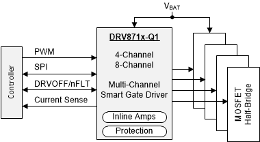
DRV871x-Q1 デバイス・ファミリは、複数のモーターまたは負荷を駆動するための高集積マルチチャネル・ゲート・ドライバです。これらのデバイスは 4 つ (DRV8714-Q1) または 8 つ (DRV8718-Q1) のハーフブリッジ・ゲート・ドライバ、ドライバ電源、電流シャント・アンプ、保護モニタを内蔵しており、システム全体の複雑さ、サイズ、コストを低減します。

スマート・ゲート・ドライブ・アーキテクチャはデッドタイムを管理して貫通電流を防止し、スルーレートを制御して電磁干渉 (EMI) を低減し、伝搬遅延を最適化して最適な性能を達成します。

ハーフブリッジまたは H ブリッジを独立して制御するための入力モードが備わっています。SPI 制御機能と組み合わせて、4 個の PWM 入力を複数のドライバの間でマルチプレクス (多重化) することができます。

広同相シャント・アンプにより、インライン電流検出機能が実現し、ウィンドウの再循環中であっても、モーター電流を連続的に測定できます。インライン検出が必要ない場合は、ローサイドまたはハイサイドのセンス構成でアンプを使用できます。

本デバイスは、一連の保護機能を搭載しており、信頼性の高いシステム動作の確実な実現に貢献します。これらの保護機能には、低電圧監視と過電圧監視、外部 MOSFET の VDS 過電流監視と VGS ゲート障害監視、オフライン・オープン負荷および短絡の診断、内部的な温度警告と過熱保護機能があります。

製品情報 (1)
部品番号 パッケージ 本体サイズ (公称)
DRV8714-Q1 VQFN (40) 6.00mm × 6.00mm
HTQFP (48) 7.00mm × 7.00mm
VQFN (56) 8.00mm × 8.00mm
DRV8718-Q1 VQFN (56) 8.00mm × 8.00mm
利用可能なパッケージについては、このデータシートの末尾にある注文情報を参照してください。
GUID-0B3A9998-5689-4E6E-B0BF-7E7129E0E59E-low.gif簡単なブロック図