JAJSGI9D October 2014 – February 2022 DS90UB948-Q1
PRODUCTION DATA
- 1 特長
- 2 アプリケーション
- 3 概要
- 4 Revision History
- 5 Pin Configuration and Functions
-
6 Specifications
- 6.1 Absolute Maximum Ratings
- 6.2 ESD Ratings
- 6.3 Recommended Operating Conditions
- 6.4 Thermal Information
- 6.5 DC Electrical Characteristics
- 6.6 AC Electrical Characteristics
- 6.7 Timing Requirements for the Serial Control Bus
- 6.8 Switching Characteristics
- 6.9 Timing Diagrams and Test Circuits
- 6.10 Typical Characteristics
-
7 Detailed Description
- 7.1 Overview
- 7.2 Functional Block Diagram
- 7.3
Feature Description
- 7.3.1 High-Speed Forward Channel Data Transfer
- 7.3.2 Low-Speed Back Channel Data Transfer
- 7.3.3 FPD-Link III Port Register Access
- 7.3.4 Oscillator Output
- 7.3.5 Clock and Output Status
- 7.3.6 LVCMOS VDDIO Option
- 7.3.7 Power Down (PDB)
- 7.3.8 Interrupt Pin — Functional Description and Usage (INTB_IN)
- 7.3.9 General-Purpose I/O (GPIO)
- 7.3.10 SPI Communication
- 7.3.11 Backward Compatibility
- 7.3.12 Adaptive Equalizer
- 7.3.13 I2S Audio Interface
- 7.3.14 Repeater
- 7.3.15 Built-In Self Test (BIST)
- 7.3.16 Internal Pattern Generation
- 7.4
Device Functional Modes
- 7.4.1
Configuration Select MODE_SEL[1:0]
- 7.4.1.1 1-Lane FPD-Link III Input, Single Link OpenLDI Output
- 7.4.1.2 1-Lane FPD-Link III Input, Dual Link OpenLDI Output
- 7.4.1.3 2-Lane FPD-Link III Input, Dual Link OpenLDI Output
- 7.4.1.4 2-Lane FPD-Link III Input, Single Link OpenLDI Output
- 7.4.1.5 1-Lane FPD-Link III Input, Single Link OpenLDI Output (Replicate)
- 7.4.2 MODE_SEL[1:0]
- 7.4.3 OpenLDI Output Frame and Color Bit Mapping Select
- 7.4.1
Configuration Select MODE_SEL[1:0]
- 7.5 Image Enhancement Features
- 7.6
Programming
- 7.6.1 Serial Control Bus
- 7.6.2 Multi-Controller Arbitration Support
- 7.6.3 I2C Restrictions on Multi-Controller Operation
- 7.6.4 Multi-Controller Access to Device Registers for Newer FPD-Link III Devices
- 7.6.5 Multi-Controller Access to Device Registers for Older FPD-Link III Devices
- 7.6.6 Restrictions on Control Channel Direction for Multi-Controller Operation
- 7.7 Register Maps
- 8 Application and Implementation
- 9 Power Supply Recommendations
- 10Layout
- 11Device and Documentation Support
- 12Mechanical, Packaging, and Orderable Information
パッケージ・オプション
メカニカル・データ(パッケージ|ピン)
- NKD|64
サーマルパッド・メカニカル・データ
- NKD|64
発注情報
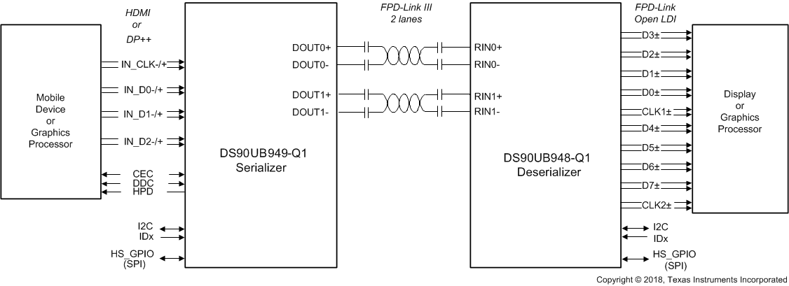
3 概要
DS90UB948-Q1 は FPD-Link III デシリアライザであり、DS90UB949A/949/947-Q1 シリアライザと組み合わせることで、1 レーンまたは 2 レーンの FPD-Link III ストリームを FPD-Link (OpenLDI) インターフェイスに変換します。このデシリアライザは、コスト効率の優れた 50Ωのシングルエンド同軸、または 100Ωの差動シールド付きツイストペア (STP) ケーブル上で動作できます。1 つまたは 2 つの FPD-Link III シリアル・ストリームからデータを回復し、デュアル・ピクセル FPD-Link (LVDS データ・レーン 8 つ + クロック) に変換して、24 ビットのカラー深度で 2K (2048×1080) までのビデオ解像度に対応できます。これによって、GPU などの HDMI 対応ソースを、既存の LVDS ディスプレイやアプリケーション・プロセッサに接続するためのブリッジとして使用できます。
FPD-Link III インターフェイスは、ビデオとオーディオのデータ転送に加えて、I2C および SPI 通信などの全二重制御機能を同じ差動リンク上でサポートします。ビデオ・データと制御を 2 つの差動ペアに統合することで、相互接続のサイズと重量が減少し、システムの設計が簡素化されます。低電圧の差動信号、データのスクランブル処理、およびランダム化を使用することで、EMI が最小限に抑えられます。下位互換モードでは、このデバイスは 1 つの差動リンクを使用し、24 ビット色深度で WXGA および 720p までの解像度に対応できます。
このデバイスは FPD-Link III チャネルを自動的に検出し、特別なトレーニング・パターンを必要とせずに、クロック同期および歪み補正機能を提供します。これによって、PCB 配線、ケーブルのペア間の長さ相違、コネクタの不均衡など、相互接続配線の不一致に起因する位相歪みに対する許容性が保証されます。
| 部品番号 | パッケージ (1) | 本体サイズ (公称) |
|---|---|---|
| DS90UB948-Q1 | WQFN (64) | 9.00mm × 9.00mm |
 代表的なアプリケーション