JAJSHO7A July 2019 – January 2021 INA253-Q1
PRODUCTION DATA
- 1 特長
- 2 アプリケーション
- 3 概要
- 4 Revision History
- 5 Pin Configuration and Functions
- 6 Specifications
-
7 Detailed Description
- 7.1 Overview
- 7.2 Functional Block Diagram
- 7.3 Feature Description
- 7.4
Device Functional Modes
- 7.4.1 Adjusting the Output Midpoint With the Reference Pins
- 7.4.2 Reference Pin Connections for Unidirectional Current Measurements
- 7.4.3 Ground Referenced Output
- 7.4.4 Reference Pin Connections for Bidirectional Current Measurements
- 7.4.5 Output Set to Mid-Supply Voltage
- 7.4.6 Output Set to Mid-External Reference
- 7.4.7 Output Set Using Resistor Divide
- 8 Application and Implementation
- 9 Power Supply Recommendations
- 10Layout
- 11Device and Documentation Support
- 12Mechanical, Packaging, and Orderable Information
3 概要
INA253-Q1 は車載用の電圧出力、電流検出アンプで、2mΩのシャント抵抗が内蔵されています。INA253-Q1 は、電源電圧にかかわらず、-4V~+80V の広い同相電圧範囲で双方向の電流を監視します。3 つの固定ゲインを利用可能:100mV/A、200mV/A、400mV/A高精度の抵抗とゼロ・ドリフトのチョップ・アンプを内蔵しているため、較正と等価の測定精度、15ppm/℃という非常に低い温度ドリフト係数、センシング抵抗に最適化されたケルビン・レイアウトが実現されています。
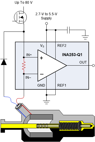
INA253-Q1 の設計には強化された PWM 除去回路が組み込まれており、大きな (dv/dt) 信号を抑制し、リアルタイムで連続的な電流測定が可能です。この測定機能は、モータ・ドライブ・アプリケーションにおけるインラインの電流測定や、ソレノイド・バルブ制御アプリケーションなどに不可欠です。
このデバイスは 2.7V~5.5V の単電源で動作し、消費電流は最大 3mA です。どのゲインのバージョンも、-40℃~+125℃の温度範囲で動作が規定され、20 ピンの TSSOP パッケージで供給されます。
製品情報 (1)
| 部品番号 | パッケージ | 本体サイズ (公称) |
|---|---|---|
| INA253-Q1 | TSSOP (20) | 6.50mm × 4.40mm |
(1) 利用可能なパッケージについては、データシートの末尾にあるパッケージ・オプションについての付録を参照してください。
 代表的なアプリケーション