JAJSH14C March 2012 – March 2019 ISO7421E-Q1
PRODUCTION DATA.
- 1 特長
- 2 アプリケーション
- 3 概要
- 4 Pin Configuration and Functions
- 5 静電気放電に関する注意事項
- 6 Absolute Maximum Ratings
- 7 Thermal Information
- 8 Recommended Operating Conditions
- 9 Electrical Characteristics
- 10Switching Characteristics
- 11Electrical Characteristics
- 12Switching Characteristics
- 13Electrical Characteristics
- 14Switching Characteristics
- 15Electrical Characteristics
- 16Switching Characteristics
- 17Parameter Measurement Information
- 18Device Information
- 19Typical Characteristics
- 20Revision History
パッケージ・オプション
メカニカル・データ(パッケージ|ピン)
- DW|16
サーマルパッド・メカニカル・データ
- DW|16
発注情報
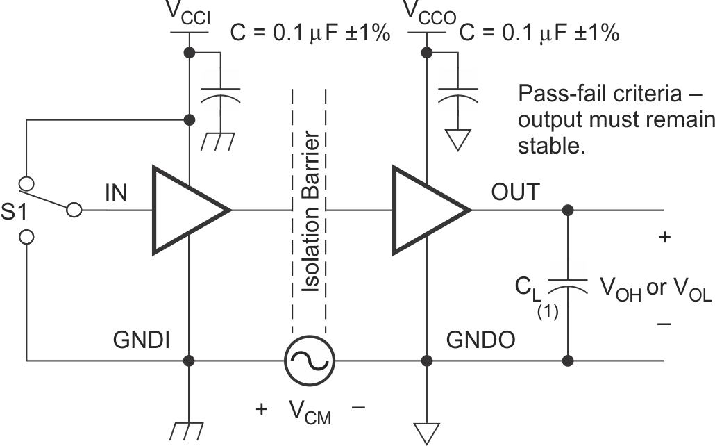
17 Parameter Measurement Information

A. The input pulse is supplied by a generator having the following characteristics: PRR ≤ 50 kHz, 50% duty cycle, tr ≤ 3ns, tf ≤ 3ns, ZO = 50Ω.
B. CL = 15 pF and includes instrumentation and fixture capacitance within ±20%.
Figure 1. Switching Characteristic Test Circuit and Voltage Waveforms 
