SNOSCY1 March 2014 LDC1041
PRODUCTION DATA.
- 1 Features
- 2 Applications
- 3 Description
- 4 Revision History
- 5 Terminal Configuration and Functions
- 6 Specifications
- 7 Detailed Description
- 8 Applications and Implementation
- 9 Power Supply Recommendations
- 10Layout
- 11Device and Documentation Support
- 12Mechanical, Packaging, and Orderable Information
1 Features
- Remote sensor placement (decoupling the LDC from harsh environments)
- High durability (by virtue of contactless operation)
- Higher flexibility for system design (using coils or springs as sensors)
- Insensitive to non-conductive environmental interferers (such as dirt, dust, oil etc.)
- Magnet-free operation
- Sub-micron precision
- Supply Voltage: 5 V, typ
- Supply voltage, IO: 1.8V to 5.5V
- Stand-by current: 250uA, typ
- Rp resolution: 8-bit
- L resolution: 24-bit
- LC frequency range: 5kHz to 5MHz
2 Applications
- Level sensing
- Proximity sensing
- Spring motion sensing
- Lateral and angular position sensing
- Metal composition detection
3 Description
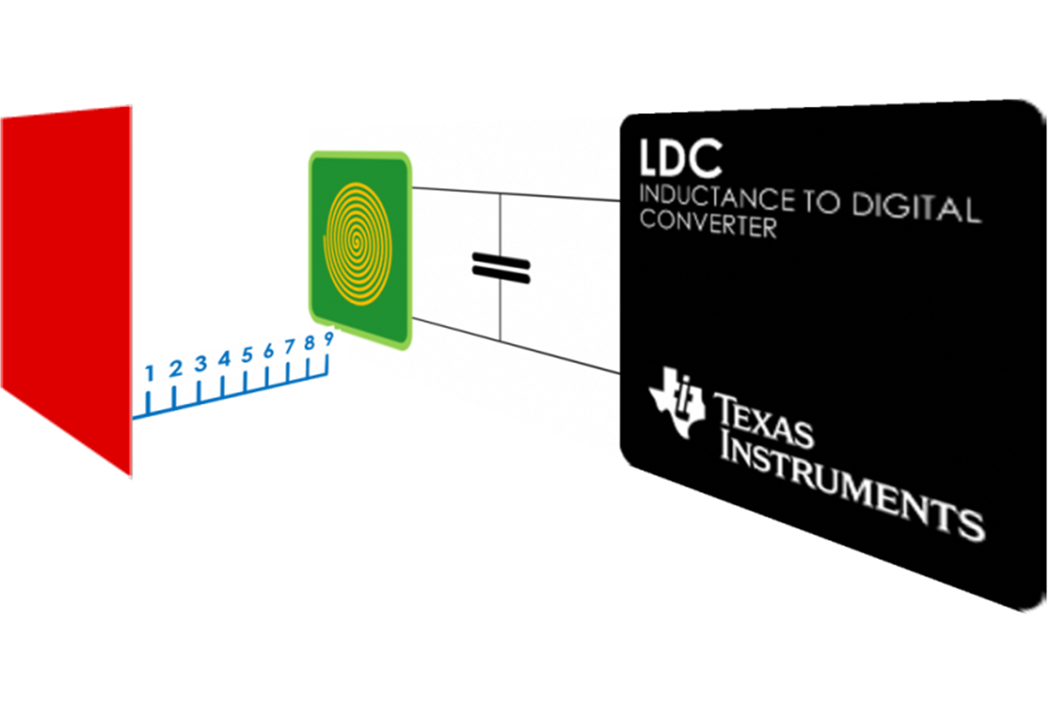
Inductive sensing is a contactless, short-range sensing technology enabling high-resolution and low-cost position sensing of conductive targets, even in harsh environments. Using a coil or spring as a sensor, the LDC1041 inductance-to-digital converter provides system designers a way to achieve high performance and reliability at a lower system cost than other competing solutions.
The LDC1041 is pin compatible with the LDC1000 (16-bit Rp/24-bit L) and the LDC1051 (8-bit Rp). This family of devices offers system designers different resolution options based on their application and system requirements.
The LDC1041 is available in a 5mm x 4mm WSON-16 package. Device programming via SPI allows for easy configuration using a microcontroller.
Device Information
| ORDER NUMBER | PACKAGE | BODY SIZE |
|---|---|---|
| LDC1041NHRT | WSON (16) | 5 mm × 4 mm |
| LDC1041NHRR | WSON (16) | 5 mm × 4 mm |
| LDC1041NHRJ | WSON (16) | 5 mm × 4 mm |
Axial Distance Sensing Application
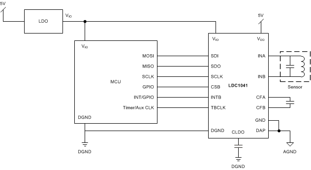
Application Schematic
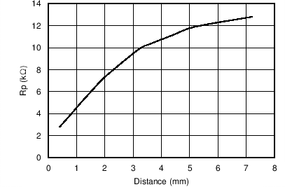
Rp vs Distance With 14mm PCB Coil
4 Revision History
| DATE | REVISION | NOTES |
|---|---|---|
| March 2014 | * | Initial release. |