JAJSM23G December 2012 – May 2021 LM25018
PRODUCTION DATA
- 1 特長
- 2 アプリケーション
- 3 概要
- 4 Revision History
- 5 Pin Configuration and Functions
- 6 Specifications
-
7 Detailed Description
- 7.1 Overview
- 7.2 Functional Block Diagram
- 7.3
Feature Description
- 7.3.1 Control Overview
- 7.3.2 VCC Regulator
- 7.3.3 Regulation Comparator
- 7.3.4 Overvoltage Comparator
- 7.3.5 On-Time Generator
- 7.3.6 Current Limit
- 7.3.7 N-Channel Buck Switch and Driver
- 7.3.8 Synchronous Rectifier
- 7.3.9 Undervoltage Detector
- 7.3.10 Thermal Protection
- 7.3.11 Ripple Configuration
- 7.3.12 Soft Start
- 7.4 Device Functional Modes
-
8 Application and Implementation
- 8.1 Application Information
- 8.2
Typical Applications
- 8.2.1 Application Circuit: 12.5-V to 48-V Input and 10-V, 325-mA Output Buck Converter
- 8.2.2 Application Curves
- 8.2.3
Typical Isolated DC-DC Converter Using LM25018
- 8.2.3.1 Design Requirements
- 8.2.3.2
Detailed Design Procedure
- 8.2.3.2.1 Transformer Turns Ratio
- 8.2.3.2.2 Total IOUT
- 8.2.3.2.3 RFB1, RFB2
- 8.2.3.2.4 Frequency Selection
- 8.2.3.2.5 Transformer Selection
- 8.2.3.2.6 Primary Output Capacitor
- 8.2.3.2.7 Secondary Output Capacitor
- 8.2.3.2.8 Type III Feedback Ripple Circuit
- 8.2.3.2.9 Secondary Diode
- 8.2.3.2.10 VCC and Bootstrap Capacitor
- 8.2.3.2.11 Input Capacitor
- 8.2.3.2.12 UVLO Resistors
- 8.2.3.2.13 VCC Diode
- 8.2.3.3 Application Curves
- 9 Power Supply Recommendations
- 10Layout
- 11Device and Documentation Support
- 12Mechanical, Packaging, and Orderable Information
パッケージ・オプション
メカニカル・データ(パッケージ|ピン)
サーマルパッド・メカニカル・データ
- DDA|8
発注情報
3 概要
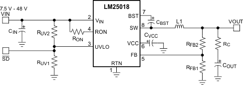
LM25018 デバイスは 48V、325mA の同期整流降圧型レギュレータで、ハイサイドとローサイドの MOSFET が内蔵されています。LM25018 に採用されているコンスタント・オンタイム (COT) 制御方式はループ補償が必要なく、過渡応答が非常に優れており、非常に高い降圧率を実現できます。オンタイムは入力電圧に反比例して変化し、入力電圧範囲の全体にわたって、周波数はほぼ一定に維持されます。高電圧のスタートアップ・レギュレータにより、IC の内部動作用および内蔵ゲート・ドライバ用にバイアス電力が供給されます。
ピーク電流制限回路により、過負荷の状況に対する保護が行われます。低電圧誤動作防止 (UVLO) 回路は、入力低電圧スレッショルドとヒステリシスを別々にプログラム可能です。その他の保護機能として、サーマル・シャットダウンとバイアス電源低電圧誤動作防止が搭載されています。
LM25018 デバイスは、WSON-8 および SO PowerPAD-8 プラスチック・パッケージで供給されます。
製品情報
| 部品番号 | パッケージ | 本体サイズ (公称) |
|---|---|---|
| LM25018 | SO PowerPAD (8) | 4.89mm × 3.90mm |
| WSON (8) | 4.00mm×4.00mm |
 代表的なアプリケーション