SNVS536F October   2007  – July 2015 LM2757

PRODUCTION DATA.  

  1. Features
  2. Applications
  3. Description
  4. Revision History
  5. Device Options
  6. Pin Configuration and Functions
  7. Specifications
    1. 7.1 Absolute Maximum Ratings
    2. 7.2 ESD Ratings
    3. 7.3 Recommended Operating Conditions
    4. 7.4 Thermal Information
    5. 7.5 Electrical Characteristics
    6. 7.6 Typical Characteristics
  8. Detailed Description
    1. 8.1 Overview
    2. 8.2 Functional Block Diagram
    3. 8.3 Feature Description
      1. 8.3.1 Efficiency Performance
      2. 8.3.2 Soft Start
      3. 8.3.3 Thermal Shutdown
      4. 8.3.4 Current-Limit Protection
    4. 8.4 Device Functional Modes
      1. 8.4.1 Enable and Voltage Mode Selection
      2. 8.4.2 Shutdown With Output High Impedance
  9. Application and Implementation
    1. 9.1 Application Information
    2. 9.2 Typical Application
      1. 9.2.1 Switched-Capacitor Boost Regulator
        1. 9.2.1.1 Design Requirements
        2. 9.2.1.2 Detailed Design Procedure
          1. 9.2.1.2.1 Recommended Capacitor Types
          2. 9.2.1.2.2 Output Capacitor And Output Voltage Ripple
          3. 9.2.1.2.3 Input Capacitor And Input Voltage Ripple
          4. 9.2.1.2.4 Flying Capacitors
          5. 9.2.1.2.5 Recommended Capacitance
        3. 9.2.1.3 Application Curves
      2. 9.2.2 USB OTG / Mobile HDMI Power Supply
      3. 9.2.3 Supercapacitor Flash Driver
      4. 9.2.4 LED Driver
  10. 10Power Supply Recommendations
  11. 11Layout
    1. 11.1 Layout Guidelines
    2. 11.2 Layout Example
  12. 12Device and Documentation Support
    1. 12.1 Device Support
      1. 12.1.1 Third-Party Products Disclaimer
    2. 12.2 Documentation Support
      1. 12.2.1 Related Documentation
    3. 12.3 Community Resources
    4. 12.4 Trademarks
    5. 12.5 Electrostatic Discharge Caution
    6. 12.6 Glossary
  13. 13Mechanical, Packaging, and Orderable Information

パッケージ・オプション

メカニカル・データ(パッケージ|ピン)
サーマルパッド・メカニカル・データ
発注情報

11 Layout

11.1 Layout Guidelines

Proper board layout helps to ensure optimal performance of the LM2757 circuit. The following guidelines are recommended:

  • Place capacitors as close to the LM2757 as possible, and preferably on the same side of the board as the device.
  • Use short, wide traces to connect the external capacitors to the LM2757 to minimize trace resistance and inductance.
  • Use a low resistance connection between ground and the GND pin of the LM2757. Using wide traces and/or multiple vias to connect GND to a ground plane on the board is most advantageous.

11.2 Layout Example
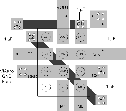
LM2757 layout_snvs536.gifFigure 28. LM2757 Layout Example