JAJS810F July   1999  – December 2016 LM50 , LM50-Q1

PRODUCTION DATA.  

  1. 特長
  2. アプリケーション
  3. 概要
  4. 改訂履歴
  5. Pin Configuration and Functions
  6. Specifications
    1. 6.1 Absolute Maximum Ratings
    2. 6.2 ESD Ratings
    3. 6.3 Recommended Operating Conditions
    4. 6.4 Thermal Information
    5. 6.5 Electrical Characteristics: LM50B
    6. 6.6 Electrical Characteristics: LM50C and LM50-Q1
    7. 6.7 Typical Characteristics
  7. Detailed Description
    1. 7.1 Overview
    2. 7.2 Functional Block Diagram
    3. 7.3 Feature Description
      1. 7.3.1 LM50 and LM50-Q1 Transfer Function
    4. 7.4 Device Functional Modes
  8. Application and Implementation
    1. 8.1 Application Information
    2. 8.2 Typical Application
      1. 8.2.1 Full-Range Centigrade Temperature Sensor
        1. 8.2.1.1 Design Requirements
        2. 8.2.1.2 Detailed Design Procedure
          1. 8.2.1.2.1 Capacitive Loads
        3. 8.2.1.3 Application Curve
    3. 8.3 System Examples
  9. Power Supply Recommendations
  10. 10Layout
    1. 10.1 Layout Guidelines
    2. 10.2 Layout Example
    3. 10.3 Thermal Considerations
  11. 11デバイスおよびドキュメントのサポート
    1. 11.1 関連リンク
    2. 11.2 ドキュメントの更新通知を受け取る方法
    3. 11.3 コミュニティ・リソース
    4. 11.4 商標
    5. 11.5 静電気放電に関する注意事項
    6. 11.6 用語集
  12. 12メカニカル、パッケージ、および注文情報

パッケージ・オプション

メカニカル・データ(パッケージ|ピン)
サーマルパッド・メカニカル・データ
発注情報

Detailed Description

Overview

The LM50 and LM50-Q1 devices are precision integrated-circuit temperature sensors that can sense a –40°C to 125°C temperature range using a single positive supply. The output voltage of the LM50 and LM50-Q1 has a positive temperature slope of 10 mV/°C. A 500-mV offset is included enabling negative temperature sensing when biased by a single supply.

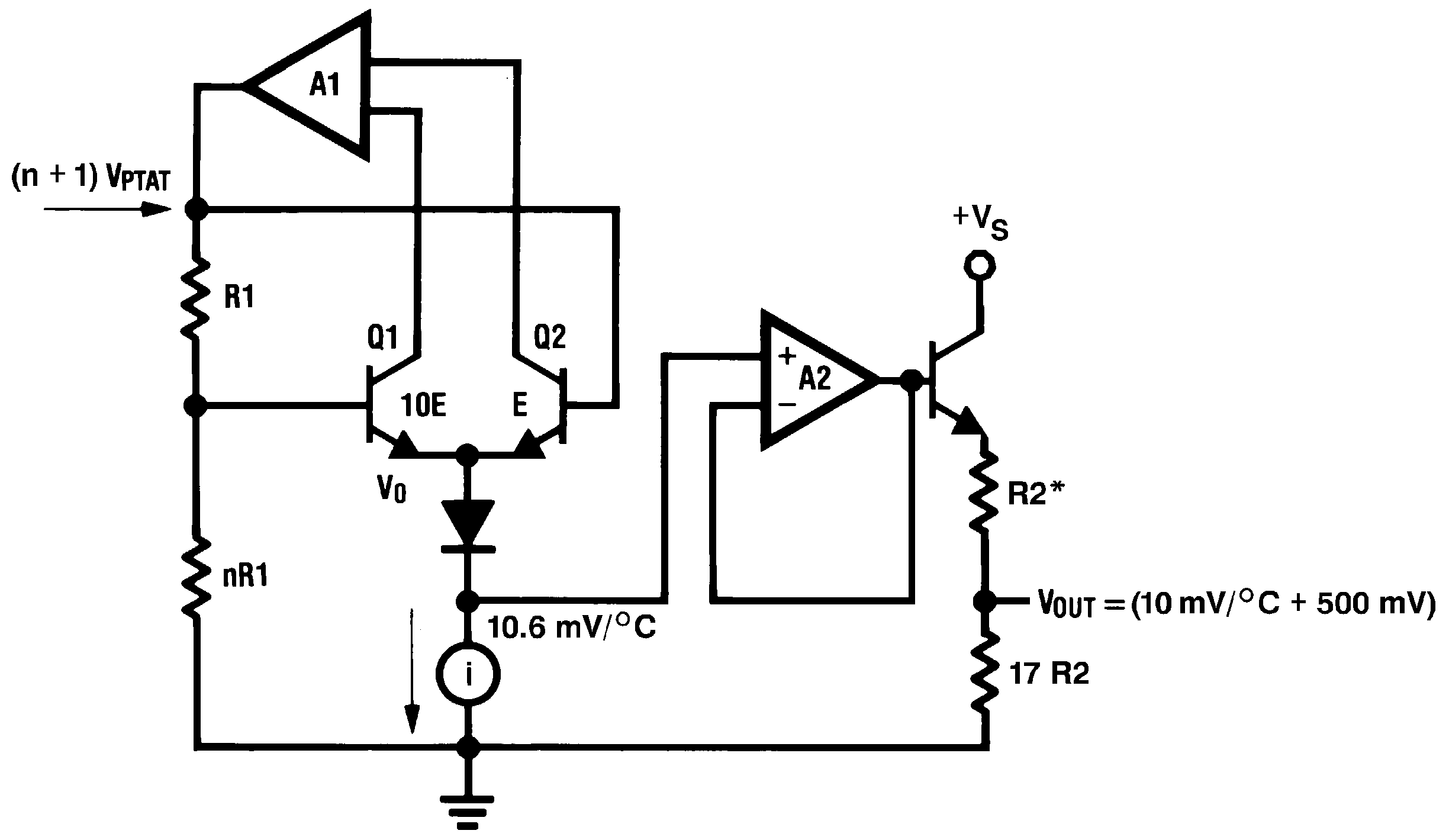
The temperature-sensing element is comprised of a delta-VBE architecture. The temperature-sensing element is then buffered by an amplifier and provided to the VOUT pin. The amplifier has a simple class A output stage with typical 2-kΩ output impedance as shown in the Functional Block Diagram.

Functional Block Diagram

LM50 LM50-Q1 01203017.png
*R2 ≈ 2k with a typical 1300-ppm/°C drift.

Feature Description

LM50 and LM50-Q1 Transfer Function

The LM50 and LM50-Q1 follow a simple linear transfer function to achieve the accuracy as listed in the Electrical Characteristics: LM50B table and the Electrical Characteristics: LM50C and LM50-Q1 table.

Use Equation 1 to calculate the value of VO.

Equation 1. VO = 10 mV/°C × T °C + 500 mV

where

  • T is the temperature in °C
  • VO is the LMT90 output voltage

Device Functional Modes

The only functional mode of the device has an analog output directly proportional to temperature.