JAJSEY4C March 2018 – October 2021 LM51501-Q1
PRODUCTION DATA
- 1 特長
- 2 アプリケーション
- 3 概要
- 4 Revision History
- 5 Device Comparison Table
- 6 Pin Configuration and Functions
- 7 Specifications
-
8 Detailed Description
- 8.1 Overview
- 8.2 Functional Block Diagram
- 8.3
Feature Description
- 8.3.1 Enable (EN Pin)
- 8.3.2 High Voltage VCC Regulator (PVCC, AVCC Pin)
- 8.3.3 Power-On Voltage Selection (VSET Pin)
- 8.3.4 Switching Frequency (RT Pin)
- 8.3.5 Clock Synchronization (SYNC Pin in SS Configuration)
- 8.3.6 Current Sense, Slope Compensation, and PWM (CS Pin)
- 8.3.7 Current Limit (CS Pin)
- 8.3.8 Feedback and Error Amplifier (COMP Pin)
- 8.3.9 Automatic Wake-Up and Standby
- 8.3.10 Boost Status Indicator (STATUS Pin)
- 8.3.11 Maximum Duty Cycle Limit and Minimum Input Supply Voltage
- 8.3.12 MOSFET Driver (LO Pin)
- 8.3.13 Thermal Shutdown
- 8.4 Device Functional Modes
-
9 Application and Implementation
- 9.1 Application Information
- 9.2
Typical Application
- 9.2.1 Design Requirements
- 9.2.2
Detailed Design Procedure
- 9.2.2.1 Custom Design With WEBENCH® Tools
- 9.2.2.2 RSET Resistor
- 9.2.2.3 RT Resistor
- 9.2.2.4 Inductor Selection (LM)
- 9.2.2.5 Current Sense (RS)
- 9.2.2.6 Slope Compensation Ramp (RSL)
- 9.2.2.7 Output Capacitor (COUT)
- 9.2.2.8 Loop Compensation Component Selection and Maximum ESR
- 9.2.2.9 PVCC Capacitor, AVCC Capacitor, and AVCC Resistor
- 9.2.2.10 VOUT Filter (CVOUT, RVOUT)
- 9.2.2.11 Input Capacitor
- 9.2.2.12 MOSFET Selection
- 9.2.2.13 Diode Selection
- 9.2.2.14 Efficiency Estimation
- 9.2.3 Application Curves
- 9.3 System Examples
- 10Power Supply Recommendations
- 11Layout
- 12Device and Documentation Support
- 13Mechanical, Packaging, and Orderable Information
パッケージ・オプション
デバイスごとのパッケージ図は、PDF版データシートをご参照ください。
メカニカル・データ(パッケージ|ピン)
- RUM|16
サーマルパッド・メカニカル・データ
発注情報
3 概要
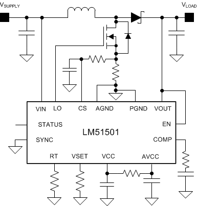
LM51501-Q1 デバイスは、入力範囲の広い自動昇圧コントローラです。このデバイスは、自動車のクランキング時に、車載バッテリやバックアップ・バッテリから安定した出力電圧を維持するために使用できます。
LM51501-Q1 のスイッチング周波数は、220kHz~2.3MHz の範囲で抵抗を使ってプログラム可能です。高速なスイッチング (2.2MHz 以上) により、AM 帯域との干渉が最小化され、ソリューション・サイズの小型化と、高速な過渡応答を実現できます。
LM51501-Q1 は、あらかじめ設定されたスタンバイ・スレッショルドよりも入力または出力電圧が高いときは IQ の低いスタンバイ・モードで動作し、出力電圧が設定されたウェークアップ・スレッショルドを下回ると自動的にウェークアップします。
このデバイスは、IQ の低いスタンバイ・モードとの間で遷移を行うことにより、軽負荷時にバッテリ駆動時間を延長します。1 本の抵抗により、目標出力レギュレーション電圧と、構成の両方をプログラムできます。その他、低いシャットダウン電流、昇圧ステータス・インジケータ、サイクル単位の可変電流制限、サーマル・シャットダウンなどの機能が搭載されています。ステータス・インジケータを使用して、昇圧を行っていないときはダイオードをバイパスし、消費電力を減らすように回路を制御できます。e-Call (緊急通報) モードでは、このデバイスで遮断スイッチを制御して、バックアップ・バッテリを保護できます。
| 部品番号 | パッケージ(1) | 本体サイズ (公称) |
|---|---|---|
| LM51501-Q1 | WQFN (16) | 4.00mm × 4.00mm |
 代表的なアプリケーション回路
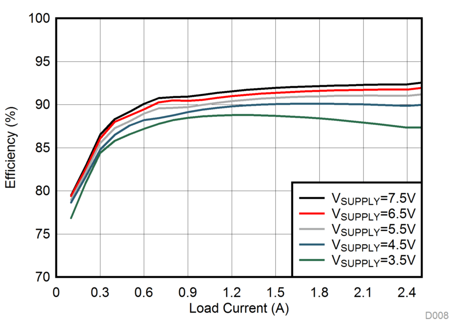
 効率 (VLOAD= 9.5V、FSW= 440kHz)