JAJSM84B december 2022 – july 2023 LM74900-Q1 , LM74910-Q1
PRODUCTION DATA
- 1
- 1 特長
- 2 アプリケーション
- 3 概要
- 4 Revision History
- 5 Device Comparison Table
- 6 Pin Configuration and Functions
- 7 Specifications
- 8 Parameter Measurement Information
-
9 Detailed Description
- 9.1 Overview
- 9.2 Functional Block Diagram
- 9.3 Feature Description
-
10Applications and Implementation
- 10.1 Application Information
- 10.2
Typical 12-V Reverse Battery Protection Application
- 10.2.1 Design Requirements for 12-V Battery Protection
- 10.2.2 Automotive Reverse Battery Protection
- 10.2.3
Detailed Design Procedure
- 10.2.3.1 Design Considerations
- 10.2.3.2 Charge Pump Capacitance VCAP
- 10.2.3.3 Input and Output Capacitance
- 10.2.3.4 Hold-Up Capacitance
- 10.2.3.5 Selection of Current Sense Resistor, RSNS
- 10.2.3.6 Selection of Scaling Resistor (RSET) and Short-Circuit Protection Setting Resistor (RSCP)
- 10.2.3.7 Overcurrent Limit (ILIM), Circuit Breaker Timer (TMR), and Current Monitoring Output (IMON) Selection
- 10.2.3.8 Overvoltage Protection and Battery Monitor
- 10.2.4 MOSFET Selection: Blocking MOSFET Q1
- 10.2.5 MOSFET Selection: Hot-Swap MOSFET Q2
- 10.2.6 TVS Selection
- 10.2.7 Application Curves
- 10.3 Addressing Automotive Input Reverse Battery Protection Topologies With LM749x0-Q1
- 10.4 Power Supply Recommendations
- 10.5 Layout
- 11Device and Documentation Support
- 12Mechanical, Packaging, and Orderable Information
パッケージ・オプション
メカニカル・データ(パッケージ|ピン)
- RGE|24
サーマルパッド・メカニカル・データ
- RGE|24
発注情報
3 概要
LM749x0-Q1 理想ダイオード・コントローラは外付けのバック・ツー・バック N チャネル MOSFET を駆動および制御して、電力パスの ON/OFF 制御と過電流および過電圧保護を備えた理想ダイオード整流器をエミュレートします。入力電源電圧範囲が 3V~65V と広いため、12V および 24V 車載用バッテリ駆動 ECU を保護および制御できます。このデバイスは最低 -65V の負の電源電圧に耐え、この電圧から負荷を保護できます。内蔵の理想ダイオード・コントローラ (DGATE) は第 1 の MOSFET を駆動し、逆入力保護および出力電圧保持用のショットキー・ダイオードを置き換えます。電力パスの第 2 の MOSFET により、過電流および過電圧が発生した場合に、HGATE 制御を使用して負荷の切断 (ON/OFF 制御) が可能です。このデバイスには電流センス・アンプが内蔵されており、可変過電流と短絡のスレッショルドにより高精度の電流監視を実現します。このデバイスには可変過電圧カットオフ保護機能があります。このデバイスにはスリープ・モードが搭載されており、非常に低い静止電流消費 (6µA) を実現すると同時に、車両が駐車状態のときは常時オンの負荷にリフレッシュ電流を供給します。LM749x0-Q1 の最高電圧定格は 65V です。
パッケージ情報
| 部品番号 | パッケージ(1) | 本体サイズ (公称) |
|---|---|---|
| LM74900-Q1 | VQFN (24) | 4.00mm × 4.00mm |
| LM74910-Q1 |
(1) 利用可能なパッケージについては、このデータシートの末尾にある注文情報を参照してください。
 代表的なアプリケーションの図
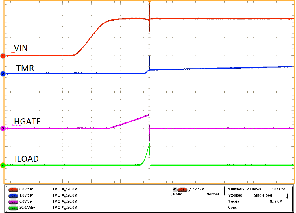
 過電流保護機能付きデバイスのスタートアップ