SNOS808P January 2000 – December 2014 LM75A
PRODUCTION DATA.
- 1 Features
- 2 Applications
- 3 Description
- 4 Revision History
- 5 Pin Configuration and Functions
- 6 Specifications
- 7 Detailed Description
- 8 Application and Implementation
- 9 Power Supply Recommendations
- 10Layout
- 11Device and Documentation Support
- 12Mechanical, Packaging, and Orderable Information
8 Application and Implementation
NOTE
Information in the following applications sections is not part of the TI component specification, and TI does not warrant its accuracy or completeness. TI’s customers are responsible for determining suitability of components for their purposes. Customers should validate and test their design implementation to confirm system functionality.
8.1 Application Information
The wide temperature and supply range and I2C interface make the LM75A ideal for a number of applications including base stations, electronic test equipment, office electronics, personal computers, and any other system where thermal management is critical to performance.
8.2 Typical Applications
8.2.1 Simple Fan Controller, Interface Optional
8.2.1.1 Design Requirements
The LM75A requires positive supply voltage of 2.7 V to 5.5 V to be applied between +Vs and GND. For best results, bypass capacitors of 100 nF and 10 µF are recommended. Pullup resistors of 10 kΩ are required on SCL and SDA.
8.2.1.2 Detailed Design Procedure
Accessing the conversion result of the LM75A consists of writing an address byte followed by retrieving the corresponding number of data bytes. The first data byte is the most significant byte with the most significant bit first, permitting only as much data as necessary to be read to determine temperature condition. For instance, if the first four bits of the temperature data indicates an overtemperature condition, the host processor could immediately take action to remedy the excessive temperatures. At the end of a read, the LM75A can accept either Acknowledge or No Acknowledge from the Master (No Acknowledge is typically used as a signal for the slave that the Master has read its last byte). Temperature data is two's complement format and one LSB is equivalent to 0.5°C.
8.2.1.3 Application Curve
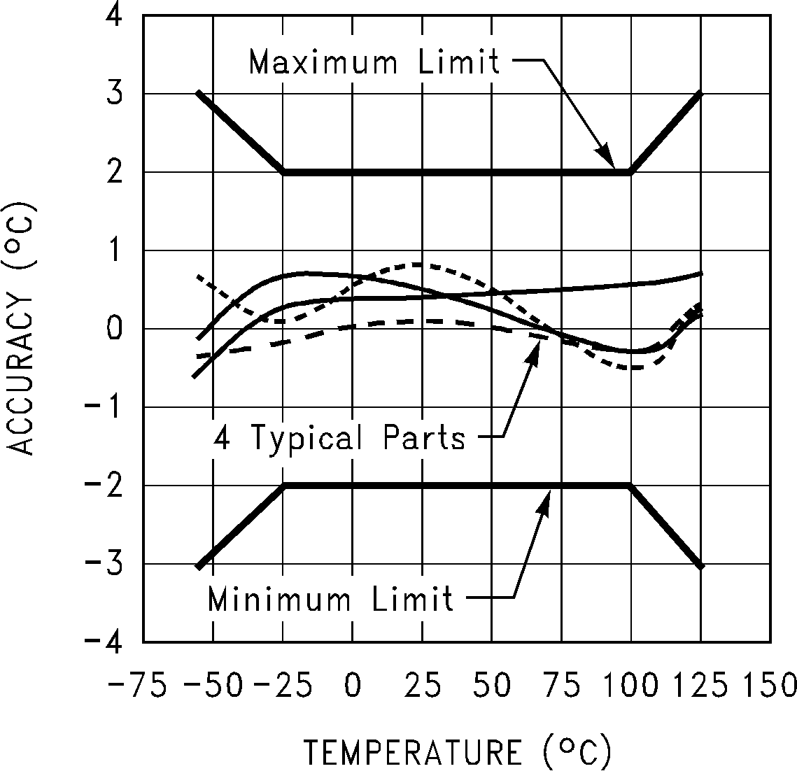 Figure 10. Temperature Accuracy