JAJSNZ3C September 2002 – June 2022 SN74HC244-Q1
PRODUCTION DATA
- 1 特長
- 2 概要
- 3 Revision History
- 4 Pin Configuration and Functions
- 5 Specifications
- 6 Parameter Measurement Information
- 7 Detailed Description
- 8 Power Supply Recommendations
- 9 Layout
- 10Device and Documentation Support
- 11Mechanical, Packaging, and Orderable Information
パッケージ・オプション
デバイスごとのパッケージ図は、PDF版データシートをご参照ください。
メカニカル・データ(パッケージ|ピン)
- DW|20
- PW|20
サーマルパッド・メカニカル・データ
- PW|20
発注情報
2 概要
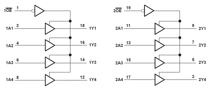
このオクタル・バッファ / ライン・ドライバは、3 ステート・メモリ・アドレス・ドライバ、クロック・ドライバ、バス用レシーバ / トランスミッタの性能と密度の両方が向上するように特に設計されています。SN74HC244 は、独立した出力イネーブル (OE) 入力を備えた 2 つの 4 ビット・バッファ / ドライバで構成されています。OE が LOW の場合、デバイスは A 入力からの非反転型データを Y 出力に渡します。OE が HIGH の場合、出力は高インピーダンス状態になります。
製品情報
| 部品番号 | パッケージ(1) | 本体サイズ (公称) |
|---|---|---|
| SN74HC244QDW-Q1 | SOIC (20) | 12.80mm × 7.50mm |
| SN74HC244QPW-Q1 | TSSOP (20) | 6.50mm × 4.40mm |
(1) 利用可能なパッケージについては、このデータシートの末尾にある注文情報を参照してください。
 機能ブロック図