JAJSOD4E January 1996 – March 2022 SN54HC365 , SN74HC365
PRODUCTION DATA
- 1 特長
- 2 概要
- 3 Revision History
- 4 Pin Configuration and Functions
- 5 Specifications
- 6 Parameter Measurement Information
- 7 Detailed Description
- 8 Power Supply Recommendations
- 9 Layout
- 10Device and Documentation Support
- 11Mechanical, Packaging, and Orderable Information
パッケージ・オプション
デバイスごとのパッケージ図は、PDF版データシートをご参照ください。
メカニカル・データ(パッケージ|ピン)
- PW|16
- NS|16
- N|16
- D|16
サーマルパッド・メカニカル・データ
発注情報
6 Parameter Measurement Information
tpd is the maximum between tPLH and tPHL
tt is the maximum between tTLH and tTHL
 Figure 6-1 Load Circuit
 Figure 6-2 Voltage Waveforms
Propagation Delay and Output Transition Times
 Figure 6-4 Voltage Waveform
Input Rise and Fall Times
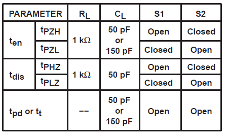
 Figure 6-3 Voltage Waveforms
Enable and Disable Times for 3-State Outputs
A. CL includes probe and jig capacitance.
B. Waveform 1 is for an output with internal conditions such that the output is low
except when diabled by the output control.
Waveform 2
is for an output with internal conditions such that the output is high except when
diabled by the output control.
C. Phase relationships between waveforms were chosen arbitrarily. All input pulses are supplied by generators having the following charactersitics: PRR ≤ 1 MHz, ZO = 50 Ω, tr = 6 ns, tf = 6 ns.
D. The outputs are measured one at a time with one input transition per measurement.
E. tPLZ and tPHZ are the same as tdis.
F. tPZL and tPZH are the same as ten.