JAJSTI8 March   2024 SN74LVC7032A

PRODUCTION DATA  

  1.   1
  2. 特長
  3. アプリケーション
  4. 概要
  5. Pin Configuration and Functions
  6. Specifications
    1. 5.1 Absolute Maximum Ratings
    2. 5.2 ESD Ratings
    3. 5.3 Recommended Operating Conditions
    4. 5.4 Thermal Information
    5. 5.5 Electrical Characteristics
    6. 5.6 Switching Characteristics
    7. 5.7 Noise Characteristics
    8. 5.8 Typical Characteristics
  7. Parameter Measurement Information
  8. Detailed Description
    1. 7.1 Overview
    2. 7.2 Functional Block Diagram
    3. 7.3 Feature Description
      1. 7.3.1 CMOS Schmitt-Trigger Inputs
      2. 7.3.2 Balanced CMOS Push-Pull Outputs
      3. 7.3.3 Clamp Diode Structure
    4. 7.4 Device Functional Modes
  9. Application and Implementation
    1. 8.1 Application Information
    2. 8.2 Typical Application
      1. 8.2.1 Design Requirements
        1. 8.2.1.1 Power Considerations
        2. 8.2.1.2 Input Considerations
        3. 8.2.1.3 Output Considerations
      2. 8.2.2 Detailed Design Procedure
      3. 8.2.3 Application Curves
    3. 8.3 Power Supply Recommendations
    4. 8.4 Layout
      1. 8.4.1 Layout Guidelines
      2. 8.4.2 Layout Example
  10. Device and Documentation Support
    1. 9.1 Documentation Support
      1. 9.1.1 Related Documentation
    2. 9.2 ドキュメントの更新通知を受け取る方法
    3. 9.3 サポート・リソース
    4. 9.4 Trademarks
    5. 9.5 静電気放電に関する注意事項
    6. 9.6 用語集
  11. 10Revision History
  12. 11Mechanical, Packaging, and Orderable Information

パッケージ・オプション

デバイスごとのパッケージ図は、PDF版データシートをご参照ください。

メカニカル・データ(パッケージ|ピン)
  • PW|14
  • BQA|14
サーマルパッド・メカニカル・データ
発注情報

概要

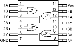
このデバイスには、シュミット トリガ入力採用の 4 つの独立した 2 入力 OR ゲートが内蔵されています。各ゲートはブール関数 Y = A + B を正論理で実行します。

パッケージ情報
部品番号パッケージ (1)パッケージ サイズ(2)本体サイズ (公称)(3)
SN74LVC7032A BQA (WQFN、14) 3mm × 2.5mm 3mm × 2.5mm
PW (TSSOP、14)5mm × 6.4mm5mm × 4.4mm
詳細については、セクション 11 を参照してください。
パッケージ サイズ (長さ×幅) は公称値であり、該当する場合はピンも含まれます
本体サイズ (長さ×幅) は公称値であり、ピンは含まれません。
GUID-108BA366-5F6A-4352-BE92-82E6007ADAED-low.gif機能的なピン配置