JAJSNV0A December   2022  – February 2023 TMAG5115

PRODUCTION DATA  

  1.   1
  2. 特長
  3. アプリケーション
  4. 概要
  5. Revision History
  6. Device Comparison
  7. Pin Configuration and Functions
  8. Specifications
    1. 7.1 Absolute Maximum Ratings
    2. 7.2 ESD Ratings
    3. 7.3 Recommended Operating Conditions
    4. 7.4 Thermal Information
    5. 7.5 Electrical Characteristics
    6. 7.6 Magnetic Characteristics
    7. 7.7 Typical Characteristics
  9. Detailed Description
    1. 8.1 Overview
    2. 8.2 Functional Block Diagram
    3. 8.3 Feature Description
      1. 8.3.1 Field Direction Definition
      2. 8.3.2 Device Output
      3. 8.3.3 Power-On Time
      4. 8.3.4 Output Stage
      5. 8.3.5 Protection Circuits
        1. 8.3.5.1 Short-Circuit Protection
        2. 8.3.5.2 Overtemperature Protection
    4. 8.4 Device Functional Modes
  10. Application and Implementation
    1. 9.1 Application Information
    2. 9.2 Typical Applications
      1. 9.2.1 Standard Circuit
        1. 9.2.1.1 Design Requirements
        2. 9.2.1.2 Detailed Design Procedure
          1. 9.2.1.2.1 Configuration Example
        3. 9.2.1.3 Application Curves
    3. 9.3 Power Supply Recommendations
    4. 9.4 Layout
      1. 9.4.1 Layout Guidelines
      2. 9.4.2 Layout Example
  11. 10Device and Documentation Support
    1. 10.1 Device Support
      1. 10.1.1 Hall Sensor Location
    2. 10.2 ドキュメントの更新通知を受け取る方法
    3. 10.3 サポート・リソース
    4. 10.4 Trademarks
    5. 10.5 静電気放電に関する注意事項
    6. 10.6 用語集
  12. 11Mechanical, Packaging, and Orderable Information

パッケージ・オプション

メカニカル・データ(パッケージ|ピン)
サーマルパッド・メカニカル・データ
発注情報

Power-On Time

After applying VCC to the TMAG5115, ton must elapse before the OUT pin is valid. During the power-up sequence, the output is Hi-Z. A pulse as shown in Figure 8-3 and Figure 8-4 occurs at the end of ton. This pulse can allow the host processor to determine when the TMAG5115 output is valid after start-up. In Case 1 (Figure 8-3) and Case 2 (Figure 8-4), the output is defined assuming a constant magnetic field B > BOP and B < BRP.
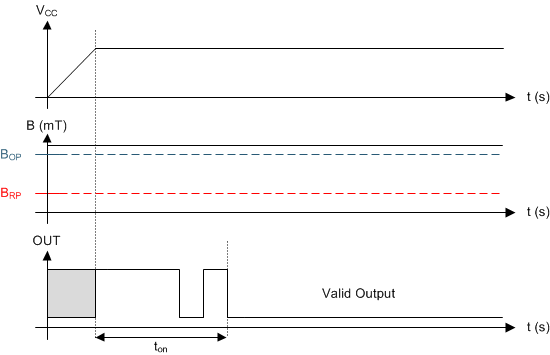
GUID-99FC0C72-9640-4690-A259-E1CBBF37C1F0-low.gif Figure 8-3 Case 1: Power On When B > BOP
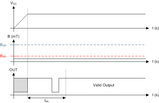
GUID-3BB42486-425A-4BF2-B6E1-B27FDC89398C-low.gif Figure 8-4 Case 2: Power On When B < BRP

If the device is powered on with the magnetic field strength BRP < B < BOP, then the device output is indeterminate and can either be Hi-Z or pulled low. During the power-up sequence, the output is held Hi-Z until ton has elapsed. At the end of ton, a pulse is given on the OUT pin to indicate that ton has elapsed. After ton, if the magnetic field changes such that BOP < B, the output is released. Case 3 (Figure 8-5) and Case 4 (Figure 8-6) show examples of this behavior.
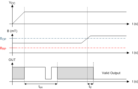
GUID-32E8259B-FCAE-4F73-ACA5-6758B0E88517-low.gif Figure 8-5 Case 3: Power On When BRP < B < BOP, Followed by B > BOP
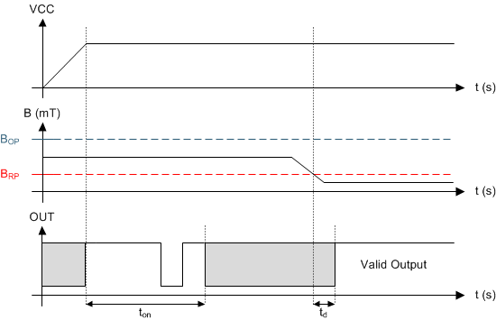
GUID-E846E994-287B-4AD0-89BD-B2E11EF4477A-low.gif Figure 8-6 Case 4: Power On When BRP < B < BOP, Followed by B < BRP