JAJSBU6B May 2013 – October 2023 TPS54531
PRODUCTION DATA
- 1
- 1 特長
- 2 アプリケーション
- 3 概要
- 4 Revision History
- 5 Pin Configuration and Functions
- 6 Specifications
-
7 Detailed Description
- 7.1 Overview
- 7.2 Functional Block Diagram
- 7.3
Feature Description
- 7.3.1 Fixed-Frequency PWM Control
- 7.3.2 Voltage Reference (Vref)
- 7.3.3 Bootstrap Voltage (BOOT)
- 7.3.4 Enable and Adjustable Input Undervoltage Lockout (VIN UVLO)
- 7.3.5 Programmable Slow Start Using SS Pin
- 7.3.6 Error Amplifier
- 7.3.7 Slope Compensation
- 7.3.8 Current-Mode Compensation Design
- 7.3.9 Overcurrent Protection and Frequency Shift
- 7.3.10 Overvoltage Transient Protection
- 7.3.11 Thermal Shutdown
- 7.4 Device Functional Modes
-
8 Application and Implementation
- 8.1 Application Information
- 8.2
Typical Application
- 8.2.1 Design Requirements
- 8.2.2
Detailed Design Procedure
- 8.2.2.1 Custom Design With WEBENCH® Tools
- 8.2.2.2 Switching Frequency
- 8.2.2.3 Output Voltage Set Point
- 8.2.2.4 Undervoltage Lockout Set Point
- 8.2.2.5 Input Capacitors
- 8.2.2.6 Output Filter Components
- 8.2.2.7 Compensation Components
- 8.2.2.8 Bootstrap Capacitor
- 8.2.2.9 Catch Diode
- 8.2.2.10 Slow-Start Capacitor
- 8.2.2.11 Output Voltage Limitations
- 8.2.2.12 Power Dissipation Estimate
- 8.2.3 Application Curves
- 8.3 Power Supply Recommendations
- 8.4 Layout
- 9 Device and Documentation Support
- 10Mechanical, Packaging, and Orderable Information
パッケージ・オプション
メカニカル・データ(パッケージ|ピン)
- DDA|8
サーマルパッド・メカニカル・データ
- DDA|8
発注情報
3 概要
TPS54531 は、低 RDS(on) のハイサイド MOSFET を内蔵した、28V、5A の非同期降圧コンバータです。軽負荷時には、パルスをスキップする Eco-mode 機能が自動的にオンになり、効率を上げます。また、シャットダウン時消費電流が 1μA と低いため、バッテリ駆動アプリケーションに使用できます。内部スロープ補償による電流モード制御により、外部補償計算が単純化され、セラミック出力コンデンサを使用しながら部品点数を減らすことができます。分圧抵抗を使用して、入力低電圧誤動作防止のヒステリシスをプログラムできます。過電圧過渡保護回路により、起動時および過渡状態での電圧オーバーシュートが制限されます。サイクル毎の電流制限方式、周波数フォールドバック、およびサーマル・シャットダウンにより、過負荷状況下でデバイスおよび負荷を保護します。TPS54531 デバイスは、熱特性向上のために内部で最適化された 8 ピン SO PowerPAD IC パッケージで供給されます。
(1) 利用可能なすべてのパッケージについては、データシートの末尾にある注文情報を参照してください。
(2) パッケージ・サイズ (長さ×幅) は公称値であり、該当する場合はピンも含まれます。
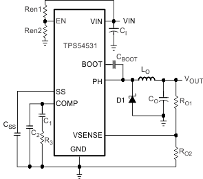
 概略回路図
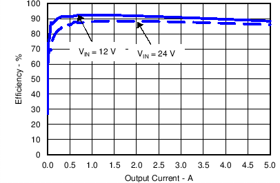
概略回路図 TPS54531 の効率