JAJSL43A July 2014 – September 2021 TPS55340-EP
PRODUCTION DATA
- 1 特長
- 2 アプリケーション
- 3 概要
- 4 Revision History
- 5 概要 (続き)
- 6 Pin Configuration and Functions
- 7 Specifications
-
8 Detailed Description
- 8.1 Overview
- 8.2 Functional Block Diagram
- 8.3
Feature Description
- 8.3.1 Switching Frequency
- 8.3.2 Voltage Reference and Setting Output Voltage
- 8.3.3 Soft Start
- 8.3.4 Slope Compensation
- 8.3.5 Overcurrent Protection and Frequency Foldback
- 8.3.6 Enable and Thermal Shutdown
- 8.3.7 Undervoltage Lockout (UVLO)
- 8.3.8 Minimum On-Time and Pulse Skipping
- 8.3.9 Layout Considerations
- 8.3.10 Thermal Considerations
- 8.4 Device Functional Modes
-
9 Application and Implementation
- 9.1 Application Information
- 9.2
Typical Applications
- 9.2.1
Boost Converter Application
- 9.2.1.1 Design Requirements
- 9.2.1.2
Detailed Design Procedure
- 9.2.1.2.1 Selecting the Switching Frequency (R4)
- 9.2.1.2.2 Determining the Duty Cycle
- 9.2.1.2.3 Selecting the Inductor (L1)
- 9.2.1.2.4 Computing the Maximum Output Current
- 9.2.1.2.5 Selecting the Output Capacitor (C8 to C10)
- 9.2.1.2.6 Selecting the Input Capacitors (C2, C7)
- 9.2.1.2.7 Setting Output Voltage (R1, R2)
- 9.2.1.2.8 Setting the Soft-Start Time (C7)
- 9.2.1.2.9 Selecting the Schottky Diode (D1)
- 9.2.1.2.10 Compensating the Control Loop (R3, C4, C5)
- 9.2.1.3 Application Curves
- 9.2.2
SEPIC Converter Application
- 9.2.2.1 Design Requirements
- 9.2.2.2
Detailed Design Procedure
- 9.2.2.2.1 Selecting the Switching Frequency (R4)
- 9.2.2.2.2 Duty Cycle
- 9.2.2.2.3 Selecting the Inductor (L1)
- 9.2.2.2.4 Calculating the Maximum Output Current
- 9.2.2.2.5 Selecting the Output Capacitor (C8 to C10)
- 9.2.2.2.6 Selecting the Series Capacitor (C6)
- 9.2.2.2.7 Selecting the Input Capacitor (C2, C7)
- 9.2.2.2.8 Selecting the Schottky Diode (D1)
- 9.2.2.2.9 Setting the Output Voltage (R1, R2)
- 9.2.2.2.10 Setting the Soft-Start Time (C3)
- 9.2.2.2.11 MOSFET Rating Considerations
- 9.2.2.2.12 Compensating the Control Loop (R3, C4)
- 9.2.2.3 SEPIC Converter Application Curves
- 9.2.1
Boost Converter Application
- 10Power Supply Recommendations
- 11Layout
- 12Device and Documentation Support
- 13Mechanical, Packaging, and Orderable Information
パッケージ・オプション
メカニカル・データ(パッケージ|ピン)
- RTE|16
サーマルパッド・メカニカル・データ
- RTE|16
発注情報
3 概要
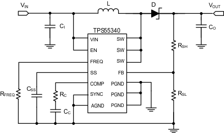
TPS55340-EP は、5A、40V のパワー・スイッチを内蔵したモノリシック非同期スイッチング・レギュレータです。このデバイスは、昇圧、SEPIC、絶縁フライバックなど、複数の標準的なスイッチング・レギュレータのトポロジに構成できます。このデバイスは広い入力電圧範囲に対応しているため、マルチセル・バッテリやレギュレートされた 3.3V、5V、12V、24V 電源レールからの入力電圧を使用するアプリケーションをサポートできます。
TPS55340-EP は電流モード PWM (パルス幅変調) 制御を使用して出力電圧をレギュレートします。また、発振器を内蔵しています。PWM のスイッチング周波数は、外付け抵抗、または外部クロック信号への同期により設定されます。ユーザーは、スイッチング周波数を
100kHz~1.2MHz の範囲でプログラムできます。
このデバイスは、プログラム可能なソフトスタート機能によりスタートアップ時の突入電流を制限します。また、その他の保護機能 (例:サイクル単位の過電流制限、サーマル・シャットダウン) も内蔵しています。
製品情報
| 発注型番 | パッケージ(1) | 本体サイズ (公称) |
|---|---|---|
| TPS55340MRTETEP | WQFN (16) | 3.00mm × 3.00mm |
(1) 利用可能なすべてのパッケージについては、このデータシートの末尾にある注文情報を参照してください。
 代表的なアプリケーション (昇圧)
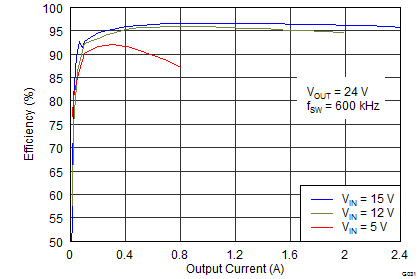
 効率と出力電流との関係