JAJSJ61J May   2020  – November 2023 TPS628501-Q1 , TPS628502-Q1 , TPS628503-Q1

PRODUCTION DATA  

  1.   1
  2. 特長
  3. アプリケーション
  4. 概要
  5. Device Comparison Table
  6. Pin Configuration and Functions
  7. Specifications
    1. 6.1 Absolute Maximum Ratings
    2. 6.2 ESD Ratings
    3. 6.3 Recommended Operating Conditions
    4. 6.4 Thermal Information
    5. 6.5 Electrical Characteristics
    6. 6.6 Typical Characteristics
  8. Parameter Measurement Information
    1. 7.1 Schematic
  9. Detailed Description
    1. 8.1 Overview
    2. 8.2 Functional Block Diagram
    3. 8.3 Feature Description
      1. 8.3.1 Precise Enable (EN)
      2. 8.3.2 COMP/FSET
      3. 8.3.3 MODE / SYNC
      4. 8.3.4 Spread Spectrum Clocking (SSC)
      5. 8.3.5 Undervoltage Lockout (UVLO)
      6. 8.3.6 Power-Good Output (PG)
      7. 8.3.7 Thermal Shutdown
    4. 8.4 Device Functional Modes
      1. 8.4.1 Pulse Width Modulation (PWM) Operation
      2. 8.4.2 Power Save Mode Operation (PWM/PFM)
      3. 8.4.3 100% Duty-Cycle Operation
      4. 8.4.4 Current Limit and Short Circuit Protection
      5. 8.4.5 Foldback Current Limit and Short-Circuit Protection
      6. 8.4.6 Output Discharge
      7. 8.4.7 Input Overvoltage Protection
  10. Application and Implementation
    1. 9.1 Application Information
      1. 9.1.1 Programming the Output Voltage
      2. 9.1.2 External Component Selection
        1. 9.1.2.1 Inductor Selection
      3. 9.1.3 Capacitor Selection
        1. 9.1.3.1 Input Capacitor
        2. 9.1.3.2 Output Capacitor
    2. 9.2 Typical Application
      1. 9.2.1 Design Requirements
      2. 9.2.2 Detailed Design Procedure
      3. 9.2.3 Application Curves
    3. 9.3 System Examples
      1. 9.3.1 Fixed Output Voltage Versions
      2. 9.3.2 Synchronizing to an External Clock
    4. 9.4 Power Supply Recommendations
    5. 9.5 Layout
      1. 9.5.1 Layout Guidelines
      2. 9.5.2 Layout Example
  11. 10Device and Documentation Support
    1. 10.1 Device Support
      1. 10.1.1 サード・パーティ製品に関する免責事項
    2. 10.2 ドキュメントの更新通知を受け取る方法
    3. 10.3 サポート・リソース
    4. 10.4 Trademarks
    5. 10.5 静電気放電に関する注意事項
    6. 10.6 用語集
  12. 11Revision History
  13. 12Mechanical, Packaging, and Orderable Information

パッケージ・オプション

メカニカル・データ(パッケージ|ピン)
サーマルパッド・メカニカル・データ
発注情報

概要

TPS62850x-Q1 はピンに互換性があり、高効率で使いやすい、1A、2A (連続)、3A (ピーク) の同期整流降圧 DC/DC コンバータのファミリです。これらのデバイスは、ピーク電流モードの制御トポロジに基づいています。これらのデバイスは、インフォテインメント、先進運転支援システムなどの車載アプリケーション用に設計されたものです。低抵抗のスイッチにより、連続で最大 2A、ピークでは 3A の出力電流を供給できます。TPS62850x-Q1 では、スイッチング周波数を 1.8MHz~4MHz の範囲で外部から調整できます。また、上記と同じ周波数範囲で、外部クロックに同期させることも可能です。PWM/PFM モードでは、負荷が軽いときに自動的にパワーセーブ・モードへ移行するため、負荷範囲全体にわたって高い効率を維持できます。このファミリは PWM モードで 1% の出力電圧精度を実現しており、出力電圧精度の高い電源の設計に役立ちます。

TPS62850x-Q1 は、SOT583 パッケージで供給されます。

製品情報
部品番号(2) パッケージ(1) 本体サイズ (公称)
TPS628501-Q1 DRL (SOT583、8) 2.10mm × 1.60mm (ピンを含む)
TPS628502-Q1
TPS628503-Q1
TPS628501-Q1 DYC (SOT583、8) 2.10mm × 1.60mm (ピンを含む)
詳細については、セクション 12 を参照してください。
製品比較表を参照してください。
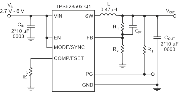
GUID-FD1A2092-6546-4309-911F-7B6A31779F43-low.gif概略回路図
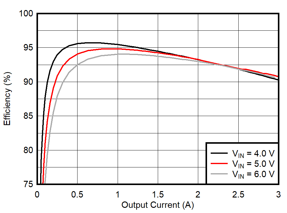
GUID-20210228-CA0I-C1XK-QHCZ-WH8H78MJXXPH-low.gif効率と IOUT との関係 (VOUT = 3.3V)