JAJS238M january 2007 – april 2023
PRODUCTION DATA
- 1
- 1 特長
- 2 アプリケーション
- 3 概要
- 4 Revision History
- 5 Pin Configuration and Functions
-
6 Specifications
- 6.1 Absolute Maximum Ratings
- 6.2 ESD Ratings
- 6.3 Recommended Operating Conditions
- 6.4 Thermal Information
- 6.5 Electrical Characteristics: Other Orderable Devices (non-M3 Suffix)
- 6.6 Electrical Characteristics: Orderable Device with M3 suffix
- 6.7 代表的特性:IOUT = 50mA
- 6.8 Typical Characteristics: IOUT = 1 A
- 6.9 Typical Characteristics: IOUT = 50 mA (M3 Suffix)
- 6.10 Typical Characteristics: IOUT = 1 A (M3 Suffix)
- 7 Detailed Description
- 8 Application and Implementation
- 9 Device and Documentation Support
- 10Mechanical, Packaging, and Orderable Information
パッケージ・オプション
メカニカル・データ(パッケージ|ピン)
サーマルパッド・メカニカル・データ
発注情報
7.5.1 Programmable Soft-Start
The TPS748 features a programmable, monotonic, voltage-controlled soft-start that is set with an external capacitor (CSS). This feature is important for many applications because soft-start eliminates power-up initialization problems when powering FPGAs, DSPs, or other processors. The controlled voltage ramp of the output also reduces peak inrush current during start-up, minimizing start-up transient events to the input power bus.
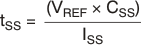
To achieve a linear and monotonic soft-start, the TPS748 error amplifier tracks the voltage ramp of the external soft-start capacitor until the voltage exceeds the internal reference. The soft-start ramp time depends on the soft-start charging current (ISS), soft-start capacitance (CSS), and the internal reference voltage (VREF), and can be calculated using Equation 2:
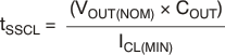
If large output capacitors are used, the device current limit (ICL) and the output capacitor can set the start-up time. In this case, the start-up time is given by Equation 3:
where:
- VOUT(nom) is the nominal output voltage
- COUT is the output capacitance
- ICL(min) is the minimum current limit for the device
In applications where monotonic start up is required, the soft-start time given by Equation 2 must be set greater than Equation 3.
The maximum recommended soft-start capacitor is 15 nF. Larger soft-start capacitors can be used and do not damage the device; however, the soft-start capacitor discharge circuit can possibly be unable to fully discharge the soft-start capacitor when enabled. Soft-start capacitors larger than 15 nF can be a problem in applications where the enable pin must be rapidly pulsed and with the device still required to soft-start from ground. CSS must be low-leakage; X7R, X5R, or C0G dielectric materials are preferred. See Table 7-2 for suggested soft-start capacitor values.
| CSS | SOFT-START TIME |
|---|---|
| Open | 0.1 ms |
| 270 pF | 0.5 ms |
| 560 pF | 1 ms |
| 2.7 nF | 5 ms |
| 5.6 nF | 10 ms |
| 10 nF | 18 ms |
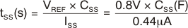 where tSS(s) = soft-start time in seconds.
Another option to set the start-up rate is to use a feedforward capacitor; see the Pros and Cons of Using a Feedforward Capacitor with a Low-Dropout Regulator application note for more information.