JAJSQ10E march   2012  – may 2023 TPS7A16-Q1

PRODUCTION DATA  

  1.   1
  2. 特長
  3. アプリケーション
  4. 説明
  5. Revision History
  6. Pin Configuration and Functions
  7. Specifications
    1. 6.1 Absolute Maximum Ratings
    2. 6.2 ESD Ratings
    3. 6.3 Recommended Operating Conditions
    4. 6.4 Thermal Information
    5. 6.5 Electrical Characteristics
    6. 6.6 Typical Characteristics
  8. Detailed Description
    1. 7.1 Overview
    2. 7.2 Functional Block Diagram
    3. 7.3 Feature Description
      1. 7.3.1 Enable (EN)
      2. 7.3.2 Regulated Output (VOUT)
      3. 7.3.3 PG Delay Timer (DELAY)
    4. 7.4 Device Functional Modes
      1. 7.4.1 Power-Good
      2. 7.4.2 Power-Good Delay and Delay Capacitor
  9. Application and Implementation
    1. 8.1 Application Information
    2. 8.2 Typical Applications
      1. 8.2.1 TPS7A1601-Q1 Circuit as an Adjustable Regulator
        1. 8.2.1.1 Design Requirements
        2. 8.2.1.2 Detailed Design Procedure
          1. 8.2.1.2.1 Adjustable Voltage Operation
          2. 8.2.1.2.2 Resistor Selection
          3. 8.2.1.2.3 Capacitor Recommendations
          4. 8.2.1.2.4 Input and Output Capacitor Requirements
          5. 8.2.1.2.5 Feed-Forward Capacitor (Only for Adjustable Version)
          6. 8.2.1.2.6 Transient Response
        3. 8.2.1.3 Application Curves
      2. 8.2.2 Automotive Applications
        1. 8.2.2.1 Design Requirements
        2. 8.2.2.2 Detailed Design Procedure
          1. 8.2.2.2.1 Device Recommendations
        3. 8.2.2.3 Application Curves
      3. 8.2.3 Multicell Battery Packs
        1. 8.2.3.1 Design Requirements
        2. 8.2.3.2 Detailed Design Procedure
        3. 8.2.3.3 Application Curves
      4. 8.2.4 Battery-Operated Power Tools
        1. 8.2.4.1 Design Requirements
        2. 8.2.4.2 Detailed Design Procedure
        3. 8.2.4.3 Application Curves
    3. 8.3 Power Supply Recommendations
    4. 8.4 Layout
      1. 8.4.1 Layout Guidelines
        1. 8.4.1.1 Additional Layout Considerations
        2. 8.4.1.2 Power Dissipation
        3. 8.4.1.3 Thermal Considerations
      2. 8.4.2 Layout Examples
  10. Device and Documentation Support
    1. 9.1 ドキュメントの更新通知を受け取る方法
    2. 9.2 サポート・リソース
    3. 9.3 Trademarks
    4. 9.4 静電気放電に関する注意事項
    5. 9.5 用語集
  11. 10Mechanical, Packaging, and Orderable Information

パッケージ・オプション

メカニカル・データ(パッケージ|ピン)
サーマルパッド・メカニカル・データ
発注情報

Battery-Operated Power Tools

High-voltage multicell battery packs support high-power applications (such as power tools) with high current drain when in use, highly intermittent use cycles, and physical separation between battery and motor.

In these applications, a microcontroller or microprocessor controls the motor. This microcontroller must be powered with a low-voltage rail coming from the high-voltage, multicell battery pack; as mentioned previously, powering this microcontroller or microprocessor from an intermediate voltage from the multicell array causes battery-pack life degradation or added system complexity because of cell balancing issues. In addition, this microcontroller or microprocessor must be protected from the high-voltage transients because of the motor inductance.

The TPS7A16-Q1 can be used to power the motor-controlled microcontroller or microprocessor; the device low quiescent current maximizes battery shelf life, and very high-voltage capabilities simplify system complexity by replacing voltage suppression filters, thus lowering system cost.
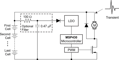
GUID-DB0BF821-EC16-45FB-9D30-179E0F0AB430-low.gifFigure 8-7 Low Power Microcontroller Power From Multicell Battery Packs in Power Tools