SLVSCE3A June   2014  – June 2014 TPS82740A , TPS82740B

PRODUCTION DATA.  

  1. Features
  2. Applications
  3. Description
    1.     Device Images
      1. 3.1 Typical Application
  4. Revision History
  5. Device Comparison Table
  6. Pin Configuration and Functions
    1.     Pin Functions
    2. Table 1. Output Voltage Setting TPS82740A
    3. Table 2. Output Voltage Setting TPS82740B
  7. Specifications
    1. 7.1 Absolute Maximum Ratings
    2. 7.2 ESD Ratings
    3. 7.3 Recommended Operating Conditions
    4. 7.4 Thermal Information
    5. 7.5 Electrical Characteristics
    6. 7.6 Typical Characteristics
  8. Parameter Measurement Information
  9. Detailed Description
    1. 9.1 Overview
    2. 9.2 Functional Block Diagram
    3. 9.3 Feature Description
      1. 9.3.1 DCS-Control
      2. 9.3.2 LOAD Switch
      3. 9.3.3 Output Voltage Selection (VSEL1, VSEL2, VSEL3)
      4. 9.3.4 Output Discharge Function (VOUT and LOAD)
      5. 9.3.5 Internal Current Limit
      6. 9.3.6 CTRL / DVS (Dynamic Voltage Scaling TPS62741)
    4. 9.4 Device Functional Modes
      1. 9.4.1 Enable / Shutdown
      2. 9.4.2 Soft Start
      3. 9.4.3 POWER GOOD OUTPUT (PG)
      4. 9.4.4 Automatic Transition into 100% Mode
  10. 10Application and Implementation
    1. 10.1 Application Information
    2. 10.2 Typical Application
      1. 10.2.1 Design Requirements
      2. 10.2.2 Detailed Design Procedure
        1. 10.2.2.1 Input Capacitor Selection
          1. 10.2.2.1.1 Input Buffer Capacitor Selection
        2. 10.2.2.2 Output Capacitor Selection
      3. 10.2.3 Application Curves
  11. 11Power Supply Recommendations
  12. 12Layout
    1. 12.1 Layout Guidelines
    2. 12.2 Layout Example
    3. 12.3 Surface Mount Information
  13. 13Device and Documentation Support
    1. 13.1 Documentation Support
      1. 13.1.1 Related Links
    2. 13.2 Trademarks
    3. 13.3 Electrostatic Discharge Caution
    4. 13.4 Glossary
  14. 14Mechanical, Packaging, and Orderable Information
    1. 14.1 Tape and Reel Information

パッケージ・オプション

デバイスごとのパッケージ図は、PDF版データシートをご参照ください。

メカニカル・データ(パッケージ|ピン)
  • SIP|9
サーマルパッド・メカニカル・データ
発注情報

Application Curves

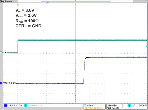
TPS82740A TPS82740B 16- Device enable and start up 2.6V.gifFigure 42. TPS82740B Device Enable and Start up
TPS82740A TPS82740B 18- Vout ramp with activated load switch 2.6V.gifFigure 44. TPS82740B VOUT Ramp with activated LOAD Switch
TPS82740A TPS82740B 17- Vout ramp after enable 2.6V.gifFigure 43. TPS82740B VOUT Ramp after Enable
TPS82740A TPS82740B 19- voltage scaling 1V8 to 2V5.gifFigure 45. TPS82740A Dynamic Output Voltage Scaling: VOUT = 1.8V / 2.5V