SLLS414F March 2000 – August 2015 TUSB2077A
PRODUCTION DATA.
- 1 Features
- 2 Applications
- 3 Description
- 4 Revision History
- 5 Description (Continued)
- 6 Pin Configuration and Functions
- 7 Specifications
- 8 Detailed Description
- 9 Application and Implementation
- 10Power Supply Recommendations
- 11Layout
- 12Device and Documentation Support
- 13Mechanical, Packaging, and Orderable Information
パッケージ・オプション
デバイスごとのパッケージ図は、PDF版データシートをご参照ください。
メカニカル・データ(パッケージ|ピン)
- PT|48
サーマルパッド・メカニカル・データ
発注情報
9 Application and Implementation
NOTE
Information in the following applications sections is not part of the TI component specification, and TI does not warrant its accuracy or completeness. TI’s customers are responsible for determining suitability of components for their purposes. Customers should validate and test their design implementation to confirm system functionality.
9.1 Application Information
A major advantage of USB is the ability to connect 127 functions configured in up to 6 logical layers (tiers) to a single personal computer.
Another advantage of USB is that all peripherals are connected using a standardized four-wire cable that provides both communication and power distribution. The power configurations are bus-powered and self-powered modes. The maximum current that may be drawn from the USB 5-V line during power up is 100 mA. For the bus-powered mode, a hub can draw a maximum of 500 mA from the 5-V line of the USB cable. A bus-powered hub must always be connected downstream to a self-powered hub unless it is the only hub connected to the PC and there are no high-powered functions connected downstream. In the self-powered mode, the hub is connected to an external power supply and can supply up to 500 mA to each downstream port. High-powered functions may draw a maximum of 500 mA from each downstream port and may only be connected downstream to self-powered hubs. Per the USB specification, in the bus-powered mode, each downstream port can provide a maximum of 100 mA of current, and in the self-powered mode, each downstream port can provide a maximum of 500 mA of current.
9.2 Typical Application
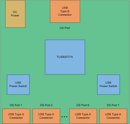
A common application for the TUSB2077A is as a self-powered USB hub product. The product is powered by an external 5-V DC Power adapter. In this application, using a USB cable TUSB2077A’s upstream port is plugged into a USB Host controller. The downstream ports of the TUSB2077A are exposed to users for connecting USB cameras, keyboards, printers, and so forth.
 Figure 8. Self-Powered USB Hub Product
9.2.1 Design Requirements
For this example, use the parameters listed in Table 2.
Table 2. Design Parameters
| DESIGN PARAMETERS | VALUE |
|---|---|
| VCC Supply | 3.3 V |
| Downstream Ports | 7 |
| Power Management | Individual Port |
| Clock Source | 6-MHz Crystal |
| External EEPROM | No |
| Power Source Mode | Self-Powered |
9.2.2 Detailed Design Procedure
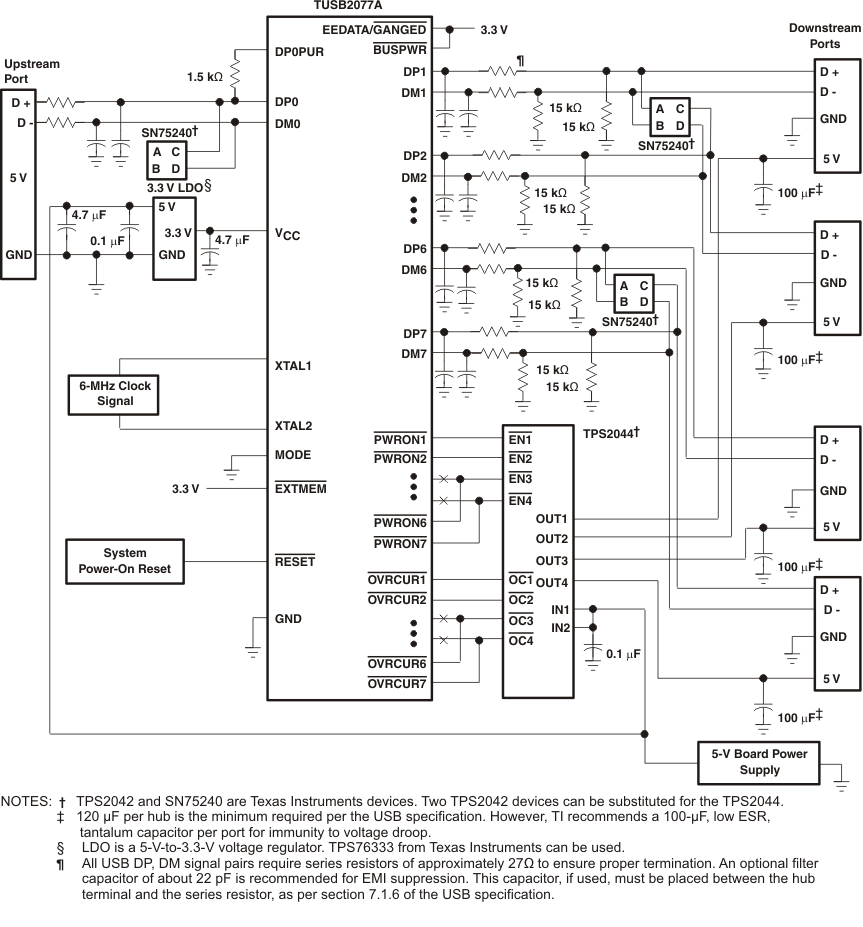
In a self-powered configuration, the TUSB2077A can be implemented for individual-port power management when used with the TPS2044 because it is capable of supplying 500 mA of current to each downstream port and can provide current limiting on a per-port basis. When the hub detects a fault on a downstream port, power is removed from only the port with the fault and the remaining ports continue to operate normally. Self-powered hubs are required to implement overcurrent protection and report overcurrent conditions. The SN75240 transient suppressors reduce inrush current and voltage spikes on the data lines.
 Figure 9. TUSB2077A Self-Powered Hub, Individual-Port Power-Management Application
9.2.3 Application Curve
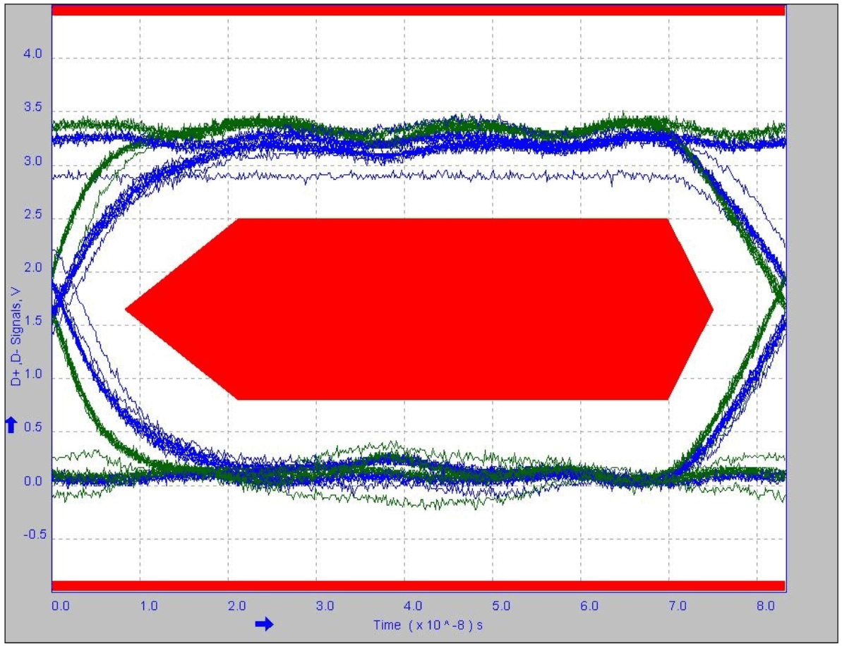
 Figure 10. Downstream Port