JAJSLC6 November 2021 UCC28781-Q1
PRODUCTION DATA
- 1 特長
- 2 アプリケーション
- 3 概要
- 4 Revision History
- 5 Pin Configuration and Functions
- 6 Specifications
-
7 Detailed Description
- 7.1 Overview
- 7.2 Functional Block Diagram
- 7.3
Detailed Pin Description
- 7.3.1 BUR Pin (Programmable Burst Mode)
- 7.3.2 FB Pin (Feedback Pin)
- 7.3.3 REF Pin (Internal 5-V Bias)
- 7.3.4 VDD Pin (Device Bias Supply)
- 7.3.5 P13 and SWS Pins
- 7.3.6 S13 Pin
- 7.3.7 IPC Pin (Intelligent Power Control Pin)
- 7.3.8 RUN Pin (Driver and Bias Source for Isolator)
- 7.3.9 PWMH and AGND Pins
- 7.3.10 PWML and PGND Pins
- 7.3.11 SET Pin
- 7.3.12 RTZ Pin (Sets Delay for Transition Time to Zero)
- 7.3.13 RDM Pin (Sets Synthesized Demagnetization Time for ZVS Tuning)
- 7.3.14 XCD Pin
- 7.3.15 CS, VS, and FLT Pins
- 7.4
Device Functional Modes
- 7.4.1 Adaptive ZVS Control with Auto-Tuning
- 7.4.2 Dead-Time Optimization
- 7.4.3 EMI Dither and Dither Fading Function
- 7.4.4 Control Law Across Entire Load Range
- 7.4.5 Adaptive Amplitude Modulation (AAM)
- 7.4.6 Adaptive Burst Mode (ABM)
- 7.4.7 Low Power Mode (LPM)
- 7.4.8 First Standby Power Mode (SBP1)
- 7.4.9 Second Standby Power Mode (SBP2)
- 7.4.10 Startup Sequence
- 7.4.11 Survival Mode of VDD (INT_STOP)
- 7.4.12
System Fault Protections
- 7.4.12.1 Brown-In and Brown-Out
- 7.4.12.2 Output Over-Voltage Protection (OVP)
- 7.4.12.3 Input Over Voltage Protection (IOVP)
- 7.4.12.4 Over-Temperature Protection (OTP) on FLT Pin
- 7.4.12.5 Over-Temperature Protection (OTP) on CS Pin
- 7.4.12.6 Programmable Over-Power Protection (OPP)
- 7.4.12.7 Peak Power Limit (PPL)
- 7.4.12.8 Output Short-Circuit Protection (SCP)
- 7.4.12.9 Over-Current Protection (OCP)
- 7.4.12.10 External Shutdown
- 7.4.12.11 Internal Thermal Shutdown
- 7.4.13 Pin Open/Short Protections
-
8 Application and Implementation
- 8.1 Application Information
- 8.2
Typical Application Circuit
- 8.2.1 Design Requirements for a 60-W, 15-V ZVSF Bias Supply Application with a DC Input
- 8.2.2 Detailed Design Procedure
- 8.2.3 Application Curves
- 9 Power Supply Recommendations
- 10Layout
- 11Device and Documentation Support
- 12Mechanical, Packaging, and Orderable Information
3 概要
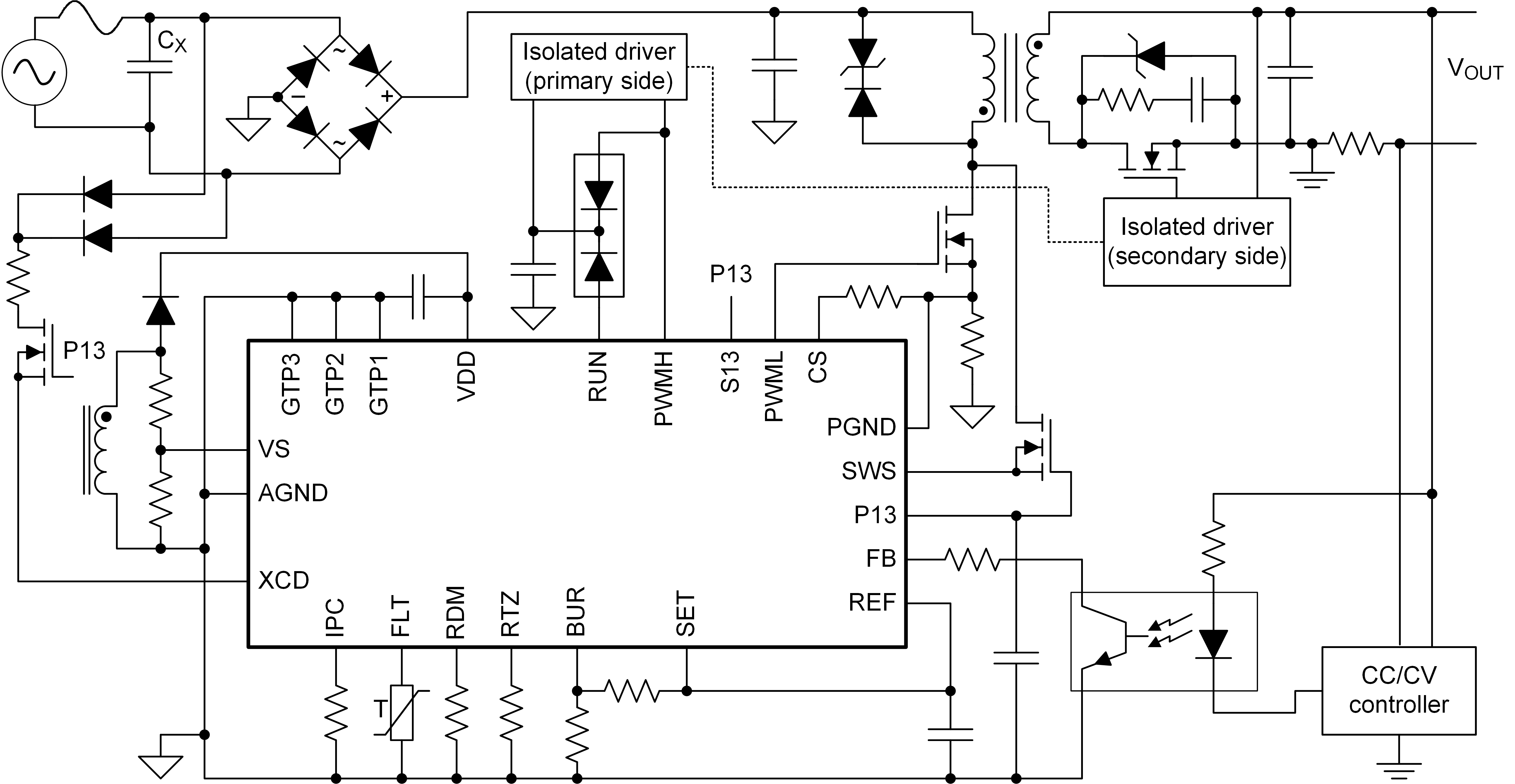
UCC28781-Q1 は、ゼロ電圧スイッチング (ZVS) コントローラであり、非常に高いスイッチング周波数で使用できるため、トランスのサイズを最小化し、高い電力密度を実現できます。
直接同期整流 (SR) 制御により、コントローラは SR FET を直接駆動して効率を最大化し、設計を簡素化できるため、個別の SR コントローラを必要としません。(絶縁型アプリケーションの場合は、絶縁型ゲート・ドライバ IC が必要です。)
ZVS 用の適応型デッドタイム制御を使用すると、スイッチング損失と EMI を最小限に抑えることができます。この設計により、コントローラは全動作範囲にわたって非常に高い変換効率を実現します。
プログラム可能な適応型バースト・モード (ABM) により、コントローラのスタンバイ・モードへの移行および終了を柔軟に制御し、軽負荷および無負荷の状況でスタンバイ電力を最適化できます。また、ABM はリップルの低減と可聴ノイズの最小化にも役立ちます。
このコントローラには、自動再起動 (再試行) 応答を備えた複数の保護モードがあります。
製品情報
| 部品番号 | パッケージ(1) | 本体サイズ |
|---|---|---|
| UCC28781-Q1 | WQFN (24) | 4.00mm × 4.00mm |
(1) 利用可能なパッケージについては、このデータシートの末尾にある注文情報を参照してください。
 アプリケーション概略