DLPU077A March   2019  – June 2019


  1.   Read This First
    1.     2
    2.     Trademarks
    3.     About This Guide
    4.     Related Documentation from Texas Instruments
  2. 1DLPDLCR660TEVM, DLPDLCR470TEVM and DLPLCRDC4422EVM Overview
    1. 1.1 Welcome
    2. 1.2 What is in the DLPDLCR660TEVM, DLPDLCR470TEVM and DLPLCRDC4422EVM Evaluation Modules (EVMs)?
    3. 1.3 EVM Boards
    4. 1.4 Other Items Needed for Operation
    5. 1.5 DLPLCRDC4422EVM, DLPDLCR470TEVM and DLPDLCR660TEVM EVM Flex Cable
  3. 2Quick Start
    1. 2.1 Downloading the Software
    2. 2.2 Connecting the DLPDLCR660TEVM, or DLPDLCR470TEVM, to the DLPLCRDC4422EVM
    3. 2.3 Powering-up the DLPLCRDC4422EVM and preparing for the DLPLCRDC4422EVM to be programmed
    4. 2.4 Programming the DLPLCRDC4422EVM and Displaying a SPLASH image
    5. 2.5 Troubleshooting
  4. 3Connections
    1. 3.1 DLPLCRDC4422EVM Connections
      1. 3.1.1 Connectors
      2. 3.1.2 TestPoints
    2. 3.2 DLPDLCR660TEVM Connections
      1. 3.2.1 Test Points
      2. 3.2.2 Connectors
    3. 3.3 DLPDLCR470TEVM Connections
      1. 3.3.1 Test Points
      2. 3.3.2 Connectors
  5. 4Power Supply Requirements
    1. 4.1 External Power Supply Requirements
  6. 5Safety
    1. 5.1 Caution Labels
    2. 5.2 If You Need Assistance
  7.   Revision History

DLPDLCR660TEVM Connections

Figure 3-2 depicts the switches and connectors with their respective locations.
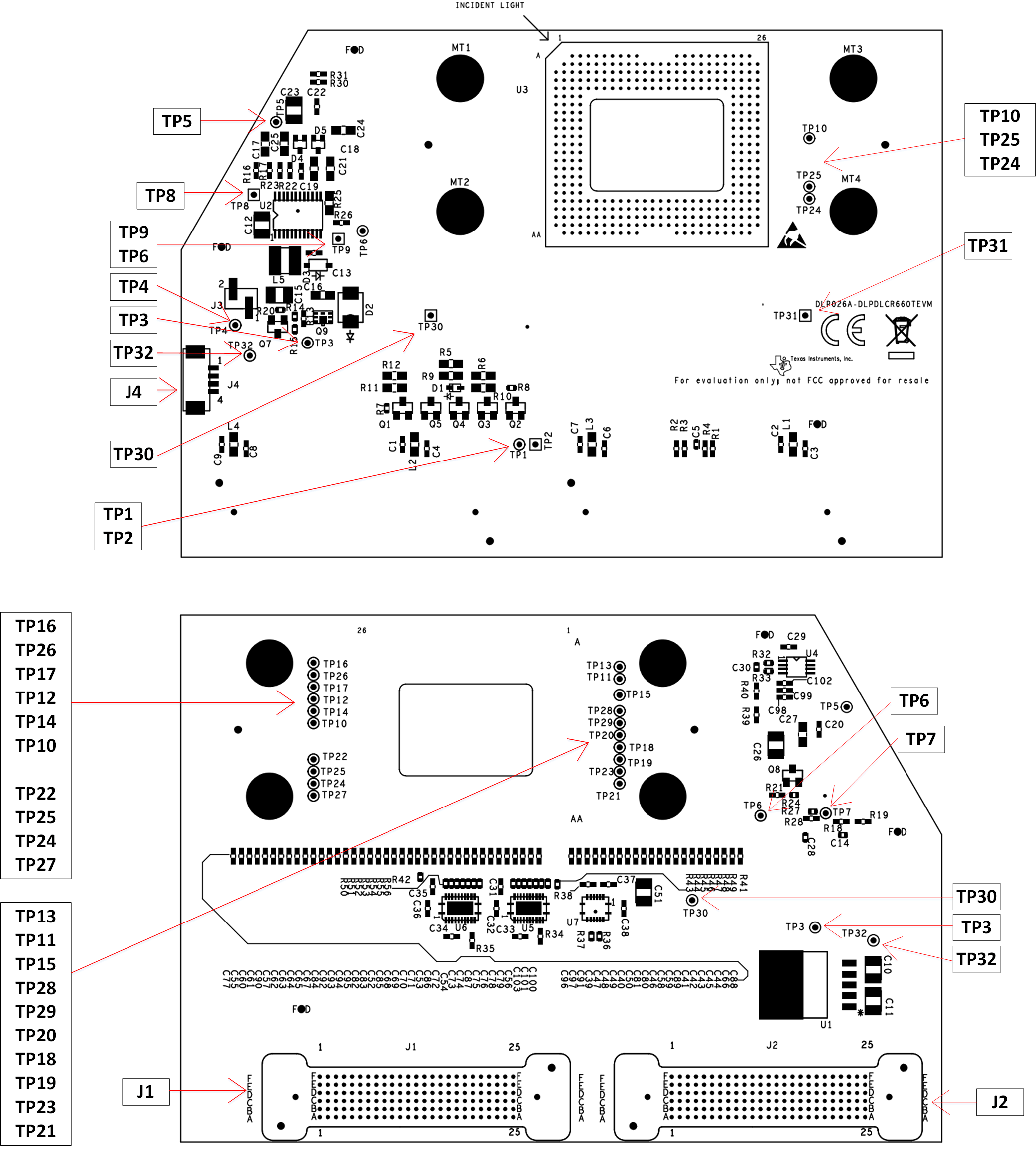
DMD_Test_Connectors.gifFigure 3-2 DLPDLCR660TEVM Test Points and Connectors