JAJSFO0G september   2012  – october 2020 SN65DSI85

PRODUCTION DATA  

  1.   1
  2. 特長
  3. アプリケーション
  4. 概要
  5. Revision History
  6. Pin Configuration and Functions
  7. Specifications
    1. 6.1 Absolute Maximum Ratings #GUID-24B27461-2407-4A70-B6CA-5D1E4961612D/SLLSEB91839
    2. 6.2 ESD Ratings
    3. 6.3 Recommended Operating Conditions
    4. 6.4 Thermal Information
    5. 6.5 Electrical Characteristics
    6. 6.6 Switching Characteristics
  8.   Parameter Measurement Information
  9. Detailed Description
    1. 7.1 Overview
    2. 7.2 Functional Block Diagram
    3. 7.3 Feature Description
      1. 7.3.1 Clock Configurations and Multipliers
      2. 7.3.2 ULPS
      3. 7.3.3 LVDS Pattern Generation
    4. 7.4 Device Functional Modes
      1. 7.4.1 Operating Modes
      2. 7.4.2 24
      3. 7.4.3 Reset Implementation
      4. 7.4.4 Initialization Sequence
      5. 7.4.5 LVDS Output Formats
      6. 7.4.6 DSI Lane Merging
      7. 7.4.7 DSI Pixel Stream Packets
      8. 7.4.8 DSI Video Transmission Specifications
    5. 7.5 Programming
      1. 7.5.1 Local I2C Interface Overview
    6. 7.6 Register Maps
      1. 7.6.1 Control and Status Registers Overview
  10. Application and Implementation
    1. 8.1 Application Information
      1. 8.1.1 Video STOP and Restart Sequence
      2. 8.1.2 Reverse LVDS Pin Order Option
      3. 8.1.3 IRQ Usage
    2. 8.2 Typical Applications
      1. 8.2.1 Typical WUXGA 18-bpp Application
        1. 8.2.1.1 Design Requirements
        2. 8.2.1.2 Detailed Design Procedure
          1. 8.2.1.2.1 Example Script
        3. 8.2.1.3 Application Curve
      2. 8.2.2 Typical WQXGA 24-bpp Application
        1. 8.2.2.1 Design Requirements
  11. Power Supply Recommendations
    1. 9.1 VCC Power Supply
    2. 9.2 VCORE Power Supply
  12. 10Layout
    1. 10.1 Layout Guidelines
      1. 10.1.1 Package Specific
      2. 10.1.2 Differential pairs
      3. 10.1.3 Ground
    2. 10.2 Layout Example
  13. 11Device and Documentation Support
    1. 11.1 Receiving Notification of Documentation Updates
    2. 11.2 Community Resources
    3. 11.3 Trademarks
  14. 12Mechanical, Packaging, and Orderable Information

概要

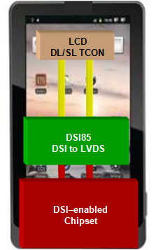
DSI から FlatLink へのブリッジである SN65DSI85 は、デュアル・チャネルの MIPI D-PHY レシーバ・フロントエンド構成で、チャネルごとに 4 レーンがあり、各レーンは 1Gbps で動作し、最大入力帯域幅は 8Gbps です。このブリッジは MIPI DSI 18bpp RGB666 および 24bpp RGB888 パケットをデコードし、フォーマットされたビデオ・データ・ストリームを、25MHz~154MHz のピクセル・クロックで動作する FlatLink 互換の LVDS 出力に変換して、リンクごとに 4 つのデータ・レーンを持つデュアル・リンク LVDS、シングル・リンク LVDS、または 2 つのシングル・リンク LVDS インターフェイスを提供します。

SN65DSI85 は、WQXGA (2560 × 1600)、毎秒 60 フレームと、WUXGA およびフル HD (1920 × 1080) 解像度で 120fps と等価の 3D グラフィック、最高 24 ビット / ピクセルに適しています。DSI と LVDS のインターフェイス間のデータ・ストリーム・ミスマッチに適応するため、部分的なライン・バッファが実装されています。

SN65DSI85 デバイスは産業用準拠のインターフェイス・テクノロジで設計されており、広範なマイクロプロセッサと互換性があり、低スイング LVDS 出力や、MIPI® 定義の超低消費電力状態 (ULPS) サポートなど、多様な電力管理機能が設計に組み入れられています。

SN65DSI85 は外形の小さな 5mm × 5mm、0.5mm ピッチの nFBGA パッケージに実装されており、-40℃~85℃の温度範囲で動作します。

製品情報(1)
部品番号 パッケージ 本体サイズ (公称)
SN65DSI85 nFBGA (64) 5.00mm × 5.00mm
利用可能なすべてのパッケージについては、このデータシートの末尾にある注文情報を参照してください。
GUID-B01D68E3-0524-4161-AE49-73038A5BE4AF-low.png代表的なアプリケーション