JAJSHR0E March   2017  – July 2022 LMH1297

PRODUCTION DATA  

  1. 特長
  2. アプリケーション
  3. 概要
  4. Revision History
  5. 概要 (続き)
  6. Pin Configuration and Functions
  7. Specifications
    1. 7.1 Absolute Maximum Ratings
    2. 7.2 ESD Ratings
    3. 7.3 Recommended Operating Conditions
    4. 7.4 Thermal Information
    5. 7.5 Electrical Characteristics
    6. 7.6 Recommended SMBus Interface Timing Specifications
    7. 7.7 Serial Parallel Interface (SPI) Timing Specifications
    8. 7.8 Typical Characteristics
  8. Detailed Description
    1. 8.1 Overview
    2. 8.2 Functional Block Diagram
    3. 8.3 Feature Description
      1. 8.3.1  4-Level Input Pins and Thresholds
      2. 8.3.2  Equalizer (EQ) and Cable Driver (CD) Mode Control
        1. 8.3.2.1 EQ/CD_SEL Control
        2. 8.3.2.2 OUT0_SEL and SDI_OUT_SEL Control
      3. 8.3.3  Input Carrier Detect
      4. 8.3.4  –6-dB Splitter Mode Launch Amplitude for SDI_IO+ (EQ Mode Only)
      5. 8.3.5  Continuous Time Linear Equalizer (CTLE)
        1. 8.3.5.1 Line-Side Adaptive Cable Equalizer (SDI_IO+ in EQ mode)
        2. 8.3.5.2 Host-Side Adaptive PCB Trace Equalizer (IN0± in CD Mode)
      6. 8.3.6  Clock and Data (CDR) Recovery
      7. 8.3.7  Internal Eye Opening Monitor (EOM)
      8. 8.3.8  Output Function Control
      9. 8.3.9  Output Driver Control
        1. 8.3.9.1 Line-Side Output Cable Driver (SDI_IO+ in CD mode, SDI_OUT+ in EQ or CD mode)
          1. 8.3.9.1.1 Output Amplitude (VOD)
          2. 8.3.9.1.2 Output Pre-Emphasis
          3. 8.3.9.1.3 Output Slew Rate
          4. 8.3.9.1.4 Output Polarity Inversion
        2. 8.3.9.2 Host-Side 100-Ω Output Driver (OUT0± in EQ or CD mode)
      10. 8.3.10 Status Indicators and Interrupts
        1. 8.3.10.1 LOCK_N (Lock Indicator)
        2. 8.3.10.2 CD_N (Carrier Detect)
        3. 8.3.10.3 INT_N (Interrupt)
      11. 8.3.11 Additional Programmability
        1. 8.3.11.1 Cable EQ Index (CEI)
        2. 8.3.11.2 Digital MUTEREF
    4. 8.4 Device Functional Modes
      1. 8.4.1 System Management Bus (SMBus) Mode
        1. 8.4.1.1 SMBus Read and Write Transaction
          1. 8.4.1.1.1 SMBus Write Operation Format
          2. 8.4.1.1.2 SMBus Read Operation Format
      2. 8.4.2 Serial Peripheral Interface (SPI) Mode
        1. 8.4.2.1 SPI Read and Write Transactions
        2. 8.4.2.2 SPI Write Transaction Format
        3. 8.4.2.3 SPI Read Transaction Format
        4. 8.4.2.4 SPI Daisy Chain
    5. 8.5 Register Maps
  9. Application and Implementation
    1. 9.1 Application Information
      1. 9.1.1 SMPTE Requirements and Specifications
      2. 9.1.2 Low-Power Optimization in CD Mode
      3. 9.1.3 Optimized Loop Bandwidth Settings for Arria 10 FPGA Applications
    2. 9.2 Typical Applications
      1. 9.2.1 Bidirectional I/O
        1. 9.2.1.1 Design Requirements
        2. 9.2.1.2 Detailed Design Procedure
        3. 9.2.1.3 Application Curves
      2. 9.2.2 Cable Equalizer With Loop-Through
        1. 9.2.2.1 Design Requirements
        2. 9.2.2.2 Detailed Design Procedure
        3. 9.2.2.3 Application Curves
  10. 10Power Supply Recommendations
  11. 11Layout
    1. 11.1 Layout Guidelines
      1. 11.1.1 Board Stack-Up and Ground References
      2. 11.1.2 High-Speed PCB Trace Routing and Coupling
        1. 11.1.2.1 SDI_IO± and SDI_OUT±:
        2. 11.1.2.2 IN0± and OUT0±:
      3. 11.1.3 Anti-Pads
      4. 11.1.4 BNC Connector Layout and Routing
      5. 11.1.5 Power Supply and Ground Connections
      6. 11.1.6 Footprint Recommendations
    2. 11.2 Layout Example
  12. 12Device and Documentation Support
    1. 12.1 Documentation Support
      1. 12.1.1 Related Documentation
    2. 12.2 Receiving Notification of Documentation Updates
    3. 12.3 サポート・リソース
    4. 12.4 Trademarks
    5. 12.5 Electrostatic Discharge Caution
    6. 12.6 Glossary
  13. 13Mechanical, Packaging, and Orderable Information

概要

LMH1297 は、12G UHD-SDI 75Ω 双方向 I/O であり、リクロッカが内蔵されています。このデバイスは、適応型ケーブル・イコライザとして入力モードに、またはデュアル・ケーブル・ドライバとして出力モードに構成可能で、システム設計者は単一の BNC を入力または出力ポートとして柔軟に使用できるため、UHD ビデオ・ハードウェアの設計が簡単になります。内蔵のリクロッカは、両方のモードで、最大 11.88Gbps までのサポートされているすべての SMPTE データ・レートへ自動的にロックします。双方向 I/O には、オンチップの 75Ω 終端およびリターン損失補償ネットワークがあり、SMPTE の厳格なリターン損失の要件を満たします。

追加の 75Ω ドライバ出力により、LMH1297 は各種のシステム機能をサポートできます。EQ (イコライザ) モードでは、この 2 番目の 75Ω ドライバをループスルー出力として使用できます。CD (ケーブル・ドライバ) モードでは、この 75Ω ドライバを 2 番目のファンアウト・ケーブル・ドライバとして使用できます。ホスト側の 100Ω ドライバは、CD モードでループバック出力として、監視用にも使用できます。

デバイス情報(1)
部品番号 パッケージ 本体サイズ (公称)
LMH1297 QFN (32) 5.00mm × 5.00mm
利用可能なパッケージについては、このデータシートの末尾にある注文情報を参照してください。
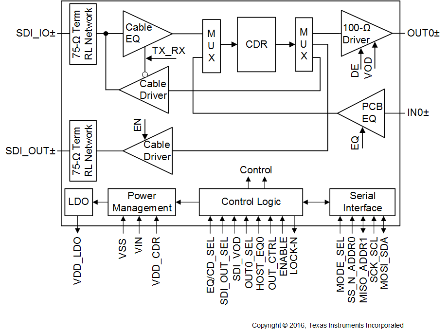
GUID-E46A8547-19A3-4692-A1DA-9C624A56DBDA-low.gif概略ブロック図