JAJU853 July   2022


  1.   概要
  2.   リソース
  3.   特長
  4.   アプリケーション
  5.   5
  6. 1System Description
  7. 2System Overview
    1. 2.1 Block Diagram
    2. 2.2 Design Considerations
      1. 2.2.1 MIL-STD-1275E versus MIL-STD-1275D
      2. 2.2.2 Reverse Polarity Event
      3. 2.2.3 Voltage Spike Event
      4. 2.2.4 Voltage Spike Event: Component Selection
      5. 2.2.5 Voltage Surge Event
      6. 2.2.6 Voltage Surge Event: Component Selection
    3. 2.3 Highlighted Products
      1. 2.3.1 LM7480-Q1
      2. 2.3.2 LM5069
  8. 3Hardware, Testing Requirements and Test Results
    1. 3.1 Hardware Requirements
    2. 3.2 Test Setup
    3. 3.3 Test Results
  9. 4Design and Documentation Support
    1. 4.1 Design Files
      1. 4.1.1 Schematics
      2. 4.1.2 BOM
    2. 4.2 Documentation Support
    3. 4.3 サポート・リソース
    4. 4.4 Trademarks

Hardware Requirements

Figure 3-1 shows the TIDA-010242 board.
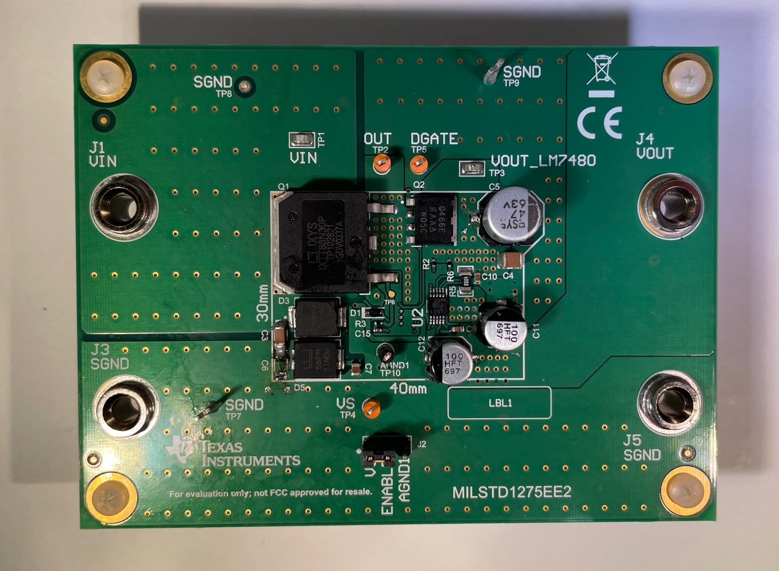
GUID-20220727-SS0I-29SV-9PKG-NZ11LT71SF2H-low.png Figure 3-1 MIL-STD-1275E board

This sections shows how to setup the TIDA-010242 for testing.

  1. Power Supply Input - Connect the input power to J1 and J3 (SGND). The nominal power supply is 28 V and put the current limit for the power supply at 5 A.
  2. Enable Jumper - Place a shunt across pin 1 and 2 of J2 to enable the device. A shunt across 2 and 3 or the shunt is DNP disables the LM7480-Q1.
  3. Power Output - The output power can be measured or connected to via J4 and J5 (SGND). These jumpers can also be used to connect to a electronic load for load testing.