JAJU885B April 2017 – January 2023
- 概要
- リソース
- 特長
- アプリケーション
- 5
-
1System Overview
- 1.1 System Description
- 1.2 Key System Specifications
- 1.3 Highlighted Products
- 1.4 Design Considerations
- 2Getting Started Hardware
- 3Testing and Results
- 4Design Files
- 5Related Documentation
- 6Trademarks
- 7Revision History
1.4.3.1 Thermal Limits
The primary maximum output current limitation in most designs is a thermal limitation. As the output current increases, the absolute power loss (in mW) in the TPS82130 also increases, which causes a higher temperature rise across the thermal impedance of the TPS82130 device.
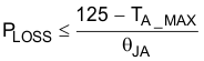
The TPS82130 data sheet recommends operating below a device temperature of 110°C and forbids operating above 125°C for reliability. Therefore, Figure 3-1 contains two thermal limit lines: one for a 110°C and one for a 125°C operating temperature. These lines are calculated by multiplying the power loss of the TPS82130 from Figure 3-2 by the θJA of the TPS82130EVM-720, which is provided in the device data sheet as 46.1 °C/W, and adding this value to a 25°C ambient temperature.
Using this method, the maximum output current at any ambient temperature can be calculated. Simply subtract the maximum ambient temperature from either 110°C or 125°C to obtain the allowable temperature rise. Divide the θJA of the printed circuit board (PCB) by this temperature rise to obtain the allowable power loss. Find this power loss in Figure 3-2 to determine the maximum output current under specific conditions. 46.1°C/W is useful as an estimate of θJA. See Equation 5 for the calculation.