SBAA548A April 2022 – May 2022 ADS8588S , ADS8681 , ADS8686S , ADS8688 , ADS8688A
3.1 Electrical Fast Transients (EFT)
The IEC 61000-4-4 standard specifies the details about the EFT test in terms of the test signals and the requirements. The purpose of the test is to verify the EFT immunity to burst stream of transient signals with short duration and fast rise time that can couple into the signal line. The standard defines four test voltage levels with two repetition frequencies for signal and control ports; 0.25 kV, 0.5 kV, 1 kV, and 2 kV at 5-kHz and 100-kHz repetition frequency. Each test covers positive and negative polarity discharge. The ADS8686S EMC test board was tested with the standard 1 kV and 2 kV, and also was tested at 4-kV levels, which are higher than required, but sometimes requested. The 100-kHz repetition frequency EFT testing is less commonly requested and more aggressive than 5 kHz. The ADS8686S EMC test board was tested at both frequencies. The EFT transient burst consists of 75 fast pulses followed by a break interval, and the burst stream is defined and tested as 15 ms for 5 kHz and 0.75 ms for 100 kHz with bursts repeated every 300 ms. Each individual burst pulse is a double exponential waveform with a rise time of 5 ns and a total pulse duration of 50 ns. The total test time for each test is approximately one minute.
Figure 3-1 shows the diagram of the setup and connection for the EFT immunity test. In this setup, the EFT threat is applied to the analog input of the ADS8686S EMC test board by running 2 m of twisted pair input wires through a 1-m length standard capacitive EFT clamp. All the cables in the test setup are kept in the insulation support. The EUT is placed on top of a ground reference plane (GRP) and isolated from the GRP by an insulating support material in 0.1-m height.
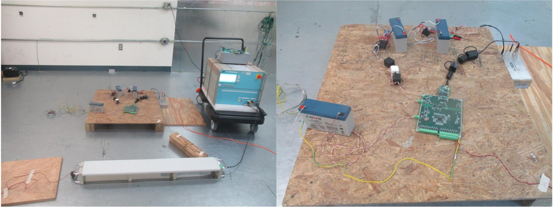
Figure 3-2 shows a photograph of the actual setup for the EFT test.
 Figure 3-2 Photograph of Laboratory Setup
for EFT Test
Figure 3-2 Photograph of Laboratory Setup
for EFT TestTable 3-1 shows the results of the EFT test.
| Test | IEC Standard | Test Signal | Test Level | Criterion | Test Result | |
|---|---|---|---|---|---|---|
| Voltage | Frequency | |||||
EFT |
IEC 61000-4-4 |
±1 kV |
5 kHz |
2 |
A |
Pass |
±2 kV |
3 |
B |
Pass |
|||
±4 kV |
4 |
B |
Pass |
|||
±1 kV |
100 kHz |
2 |
A |
Pass |
||
±2 kV |
3 |
B |
Pass |
|||
±4 kV |
4 |
B |
Pass |
|||