SBOA535 February 2022 INA190
4 Control of the FET
When designing a multiple-range topology, logic is typically required in such a design, as the gate controls of the P-channel FETs used to move from range to range must be known, and kept track of for robust system performance and protection. The reason for this is that the output signal of the current sense amplifier is repetitive from range to range. For example, consider the output point of 3 V in the design. Output of 3 V is achievable in either of the designed ranges, corresponding to 1.2 mA in the lower region, and 61.1 mA in the upper region. From a steady-state perspective, the solution necessary is simple: take the state of the P-channel gate into account via the state of the pin controlling the gate, and code the system to decipher the measurement via the appropriate shunt resistance value held in memory.
This scenario becomes more complicated, however, during initialization of the system. The recommended solution is to always begin in the highest state, and then through comparison of the signal in logic, step down to the appropriate range. The importance of this approach is that resistance values of lower ranges may have unintended effects with the current draw of the upper range, potentially leading to overpower or brownout effects on the system as the burden voltage becomes dominant against the load voltage of the line.
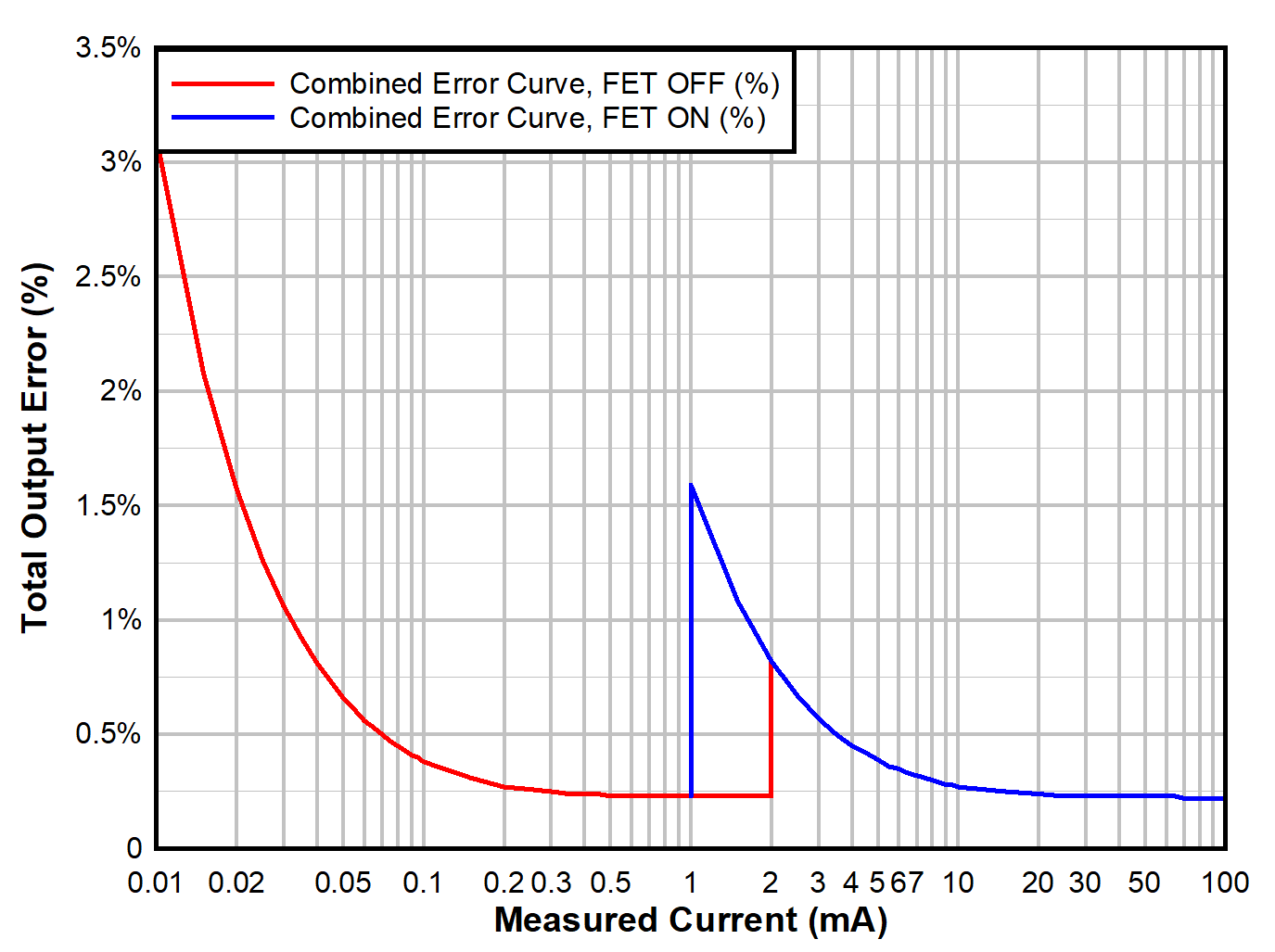
Finally, dependent on the volatility of the current signal under measurement, as well as the nominal operating ranges, it may be necessary to design hysteresis into the measurement loop to prevent unintended jitter in the measurement algorithm. While the spread of values is typically application dependent, Total Output Error (%) Over Measurement Range, 10µA to 100mA, with Hysteresis shows an exaggerated error curve, where the system transitions to the upper range when the load becomes larger than 1.5 mA, but does not return to the lower state until the current falls below
1 mA. Regardless of state, observe that the worst-case total error remains below 5%, and practically below 3%, for the totality of the range, thus satisfying the original design specification.
 Figure 4-1 Total Output Error (%) Over
Measurement Range, 10 µA to 100 mA, With Hysteresis