SBOA575 September 2023 INA823 , OPA2387 , XTR115 , XTR116
1 Introduction
Following are the design requirements:
- Use reference voltages of the current loop transmitter to power sensor and amplifier circuitry
- Total current consumption < 3.5-mA
- Weight range = 0 to 20-lbs → output current = 4 to 20-mA
- ±0.1% accuracy
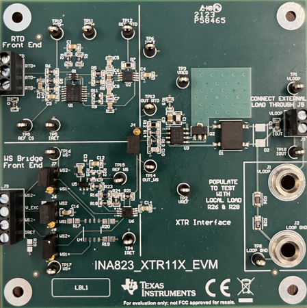
The design goals and performance are summarized in Table 5-2. The measured transfer function and completed PCB design are shown below.
Table 1-1 Design Goal versus Calculated, Simulated, and Measured Performance
| Weight | Goal | Calculated | Simulated | Measured | |
|---|---|---|---|---|---|
| Iout (Min) | 0lbs | 4mA | 4.0959mA | 4.0963mA | 4.0994mA |
| Iout (Max) | 20lbs | 20mA | 20.1404mA | 20.1397mA | 20.1545mA |
 Figure 1-1 Measured Output Current vs
Weight Transfer Function
 Figure 1-2 Wheatstone Bridge to 4-20-mA
Current Loop Transmitter PCB Design