SCDU026 July 2021
- Trademarks
- 1 Introduction
- 2 General Texas Instruments High Voltage Evaluation Module (TI HV EVM) User Safety Guidelines
- 3 Information About Cautions and Warnings
- 4 Features
- 5 TMUX-24PW-EVM Header Connections and Test Points
- 6 TMUX-24PW-EVM Setup
- 7 Layout
- 8 Schematics
- 9 Bill of Materials
- 10Revision History
8 Schematics
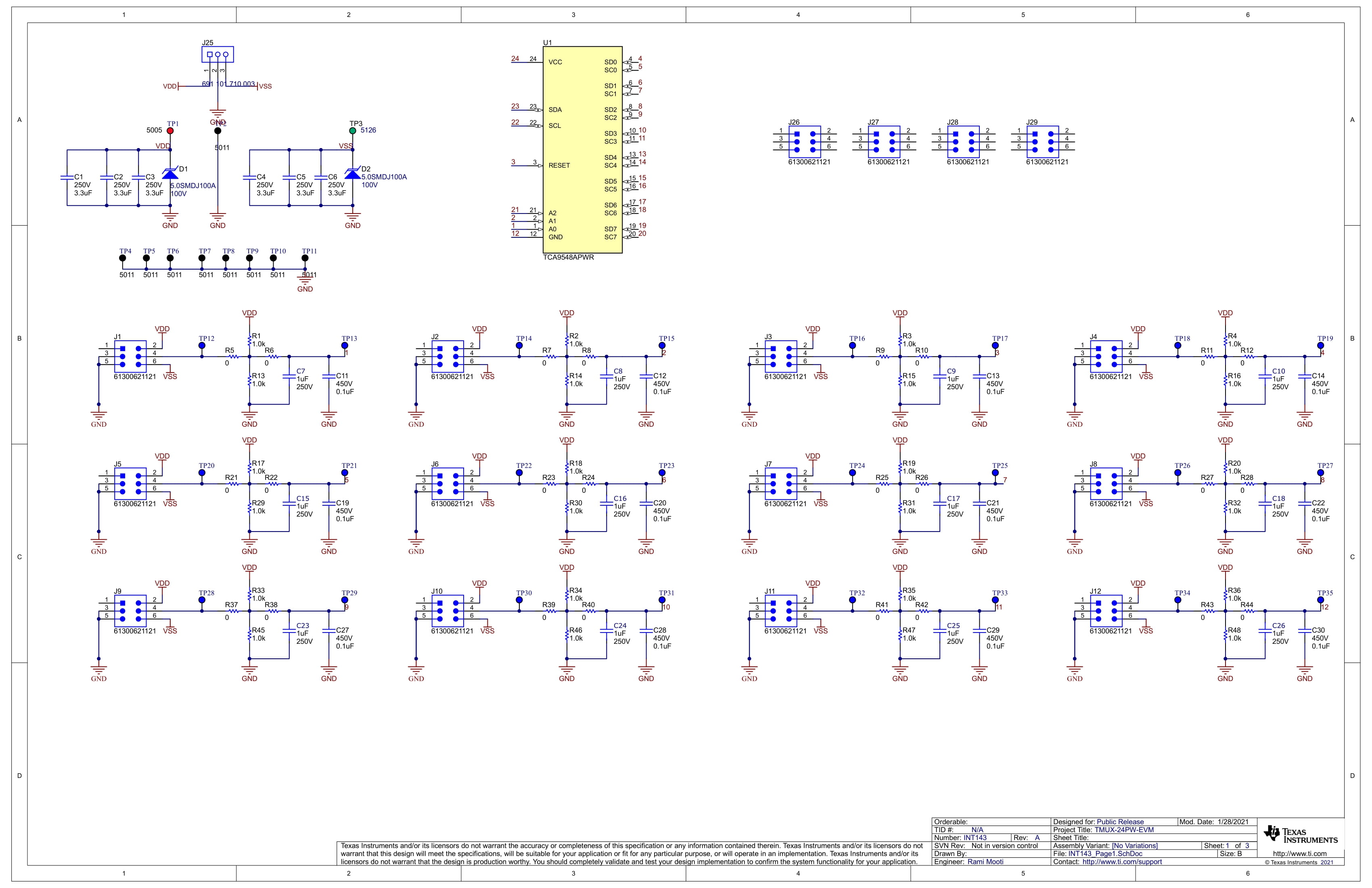
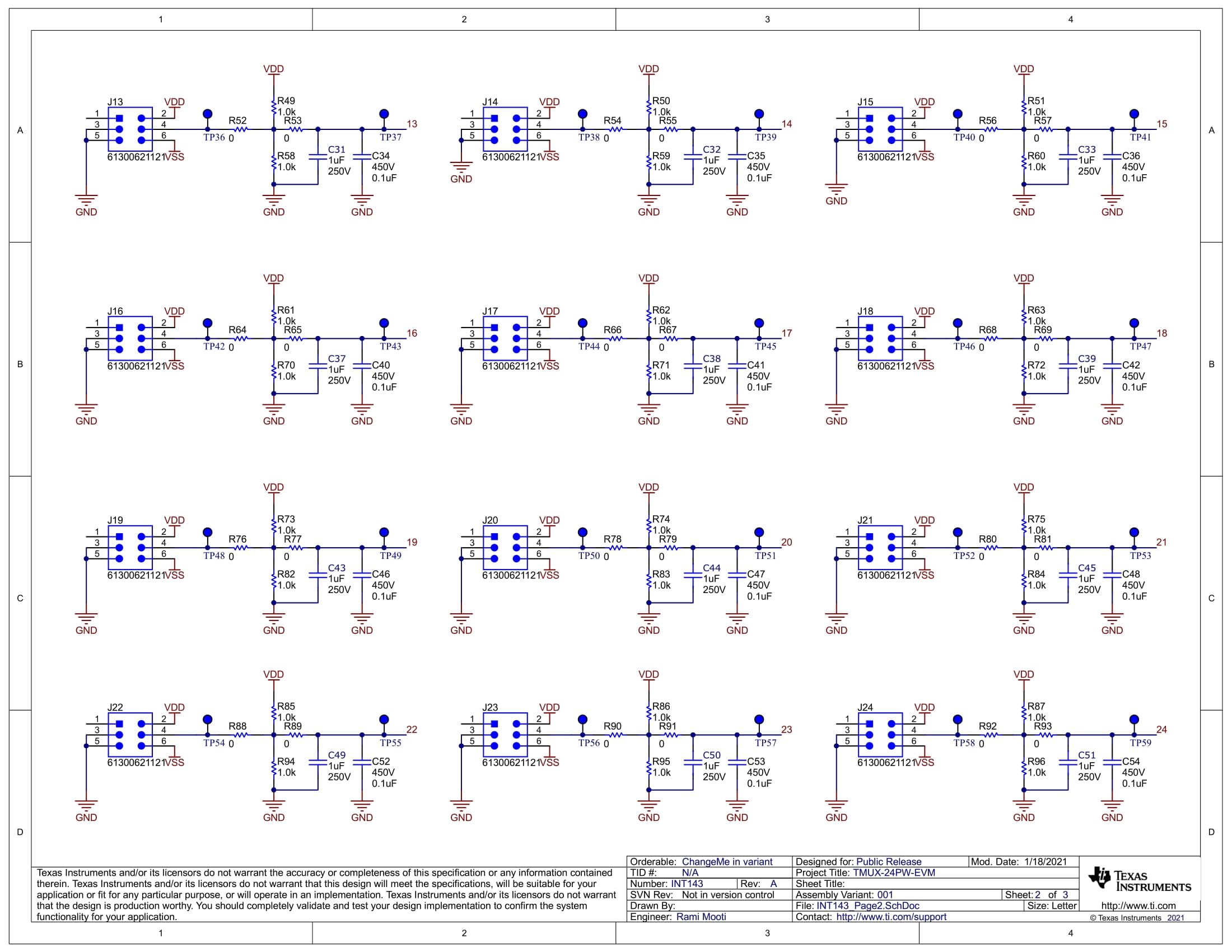
Figure 8-1 and Figure 8-2 are schematic views of the TMUX-24PW-EVM that includes all the parts and connections.
 Figure 8-1 TMUX-24PW-EVM Schematic Page 1 (Editor View)
 Figure 8-2 TMUX-24PW-EVM Schematic Page 2 (Editor View)
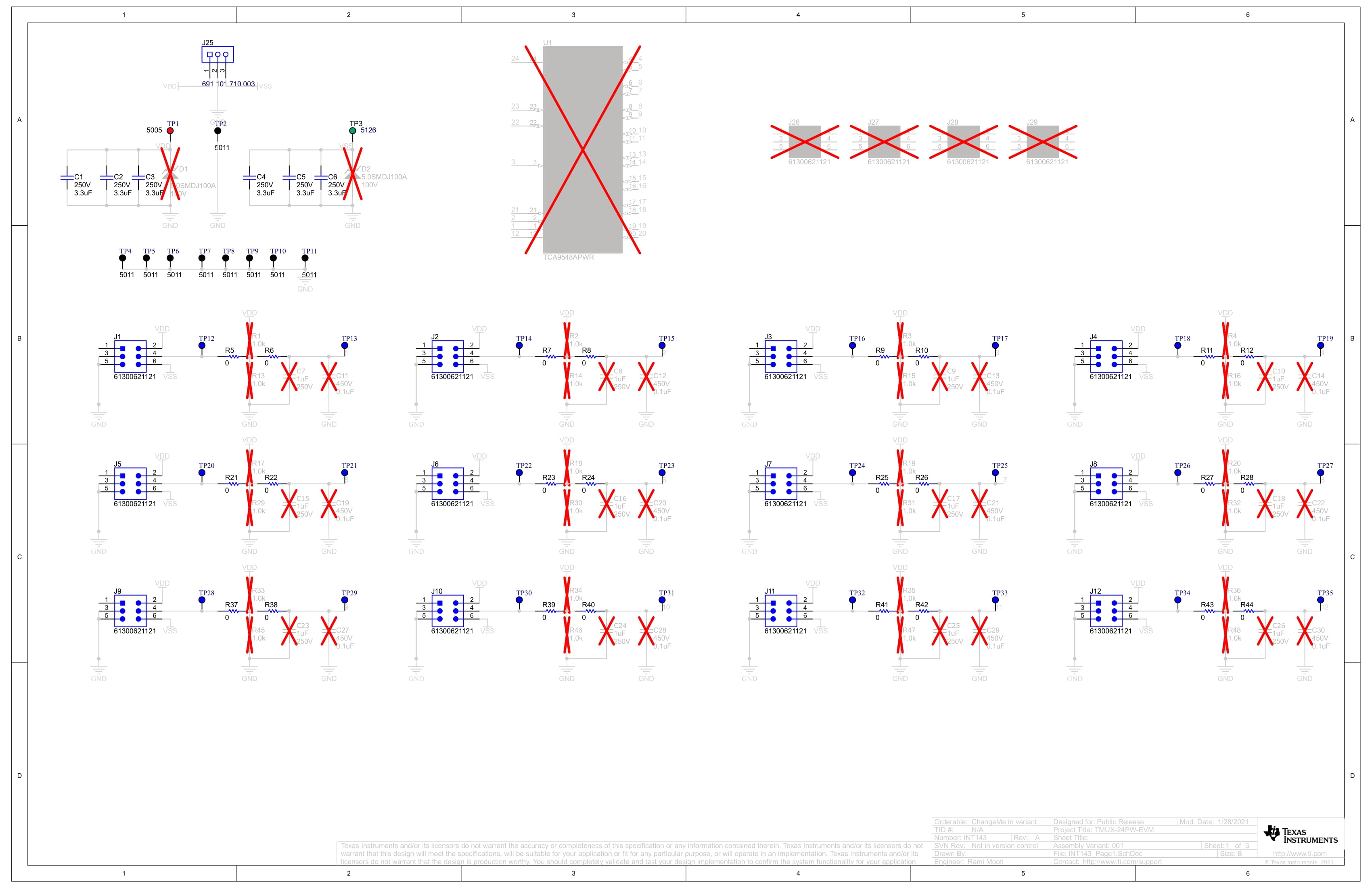
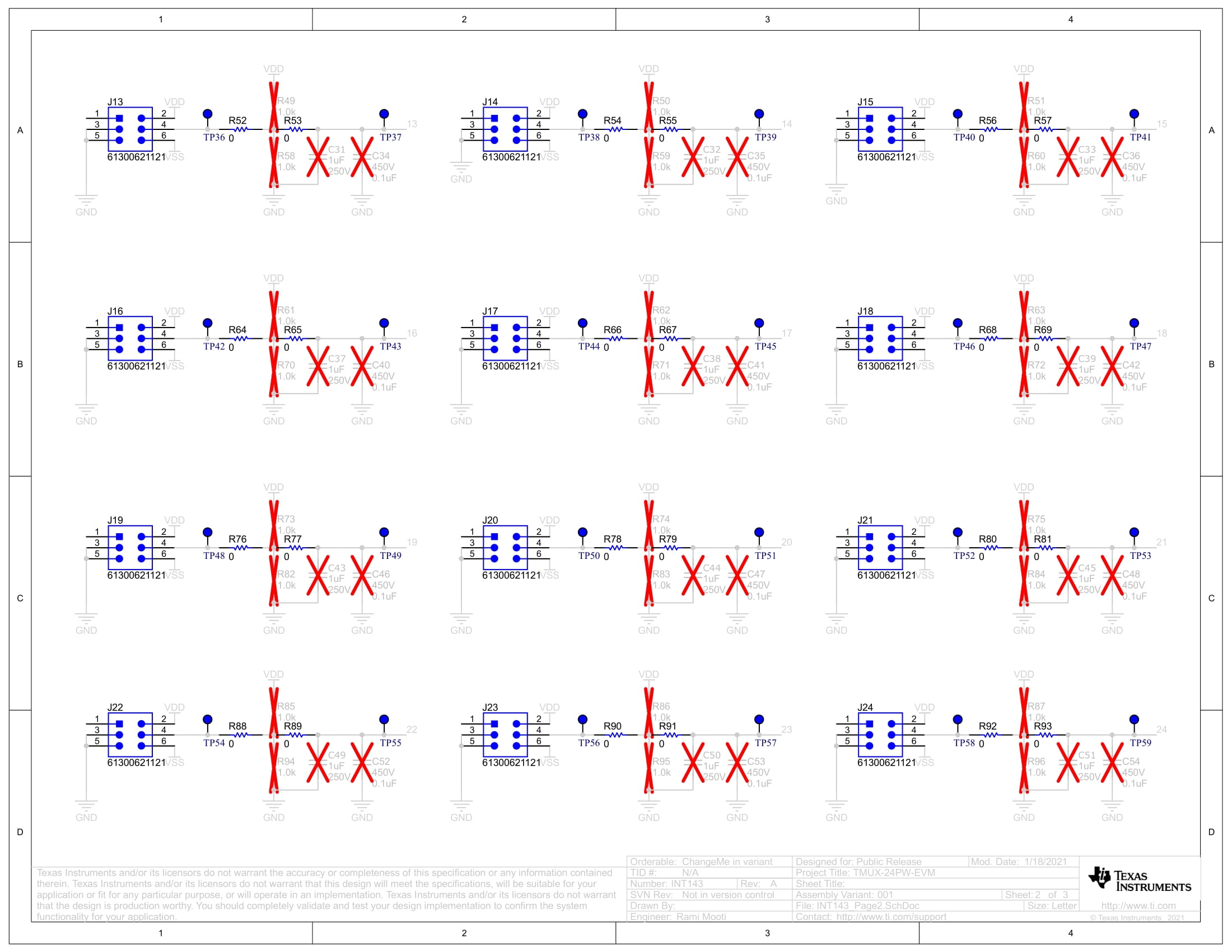
Figure 8-3 and Figure 8-4 are schematic views of the TMUX-24PW-EVM that show only the parts that are included in the EVM and excludes the parts that are DNI.
 Figure 8-3 TMUX-24PW-EVM Schematic Page 1 (DNI)
 Figure 8-4 TMUX-24PW-EVM Schematic Page 2 (DNI)