SCPU047 December 2022 TCA39416
4 Enabling Pull-up Resistors
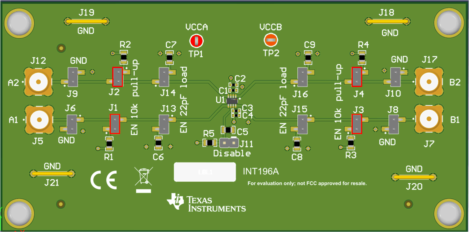
Pull-up resistors can be enabled by placing a jumper on J1, J2, J3, and J4. Pull-up resistors values are 10k with 1% tolerance. An image below shows the location of the headers with a red square to indicate jumpers to short VCC to the bus.
 Figure 4-1 Enabling Pull-Up Resistor