SLAA907D September 2019 – December 2021 PGA450-Q1 , PGA460 , PGA460-Q1 , TDC1000 , TDC1000-Q1 , TDC1011 , TDC1011-Q1 , TUSS4440 , TUSS4470
2.6 Transducer Drive (Transformer Drive & Direct Drive) and Current Limit
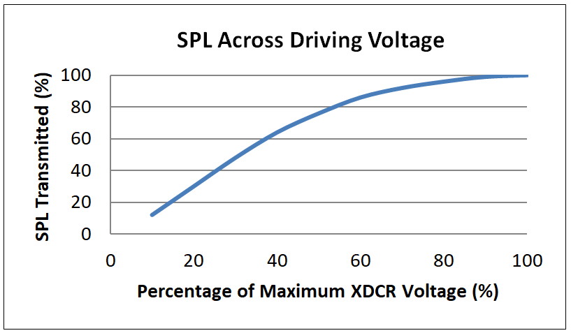
There are two ways to drive a transducer: in transformer mode or in direct drive mode. This is determined based on the maximum drive voltage (thus a higher current limit) of the selected transducer. Although direct drive is the lower-cost driving technique, it is typically intended for short range, open-top applications. Transformer drive maximizes closed-top transducer requirements (beyond 100 Vpp), but it also requires additional calibration at mass production. Figure 2-9 shows the non-linear relationship between transducer (XDCR) drive voltage, and the percent of the sound pressure level that is transmitted. Note that blindspot lengths increase with higher current limits.
 Figure 2-9 SPL Across Driving Voltage