SLAAE50A January 2022 – October 2022 MSP430FR2533 , MSP430FR2533
3.1 System Design
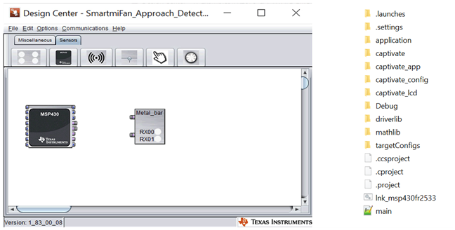
Configure the GUI. Configure the corresponding MCU and virtual sensors and generate the program source code. Refer to the CapTIvate handbook for the specific process. Figure 3-1 shows the capacitive touch project file and the generated source code
 Figure 3-1 Capacitive Touch Project File and Generated Source Code
Figure 3-2 shows the important parameter relationships in CapTIvate, where the parameters are relevant to the liquid level detection
 Figure 3-2 Parameter Relationships
The parameters are divided into hardware configuration parameters and software configuration parameters. First, the sampling module generates raw data by detecting the external capacitance. Conversion Count and Conversion Gain determine the gain of the sampling module. Then the data passes through the optional anti-noise module (sampling frequency spread spectrum, oversampling, and other functions) to achieve noise filtering. The output data is first compared to the Error Threshold. Then filterCount is generated through IIR filtering of different intensities, which is used to characterize real-time capacitance changes, and LTA (long time average, default is 7) is used to characterize the base capacitance of the environment. Here filterCount corresponds to "Count" in the GUI data monitoring module, and LTA corresponds to "LTA". The Delta between the two is used to characterize the change of capacitance generated by a touch. The relationship between the capacitance change percentage caused by the touch and the filterCount and LTA is shown in Equation 5. For self-capacitance detection, Delta is a positive value.