SLAU533D September 2013 – April 2017
-
MSP430F5529 LaunchPad™ Development Kit (MSP‑EXP430F5529LP)
- Trademarks
- 1 Getting Started
- 2
Hardware
- 2.1 Block Diagram
- 2.2
Hardware Features
- 2.2.1 MSP430F5529
- 2.2.2 eZ-FET lite Onboard Emulator
- 2.2.3 Integrated Full-Speed USB Hub
- 2.2.4 Power
- 2.2.5 Clocking
- 2.2.6 Application (or "Backchannel") UART
- 2.2.7 Emulator and Target Isolation Jumper Block
- 2.2.8 Isolation Jumper Block: 3.3-V and 5-V Jumpers
- 2.2.9 Isolation Jumper Block: Emulator Connection and Application UART
- 2.3 Measure Current Draw of MSP430 MCU
- 2.4 Using an External Power Source
- 2.5 Using the eZ-FET lite Emulator With a Different Target
- 2.6 USB BSL Button
- 2.7 BoosterPack Plug-in Module Pinout
- 2.8 Design Files
- 2.9 Hardware Change Log
- 3
Software Examples
- 3.1 MSP430 Software Libraries: driverlib and the USB API
- 3.2 Viewing the Code
- 3.3 Example Project Software Organization
- 3.4 USB Configuration Files
- 3.5 Out-of-Box Experience: emulStorageKeyboard
- 3.6 Example: simpleUsbBackchannel
- 3.7 Starting Device Manager
- 4 Additional Resources
- 5 FAQs
- 6 Schematics
- Revision History
2.2.4 Power
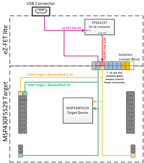
Figure 13 shows the power segment of the block diagram.
USB hosts supply a 5-V power rail to USB devices, called "VBUS". This is convenient for USB devices; if they only need to function while attached to a host (for example, mice or keyboards) then they may not need their own power source. Even if they need to function apart from the USB host and, thus, need their own power source, being attached to the host places power demands on that device which may not be present when the device is not attached; the availability of VBUS can help offset these demands.
The F5529 LaunchPad development kit has a high-efficiency dc-dc converter, a TPS62237, that derives a new power rail of 3.3 V from VBUS. This 3.3-V rail sources the eZ-FET lite, hub, target F5529 device, and the 3.3-V pin on the BoosterPack plug-in module header.
VBUS is still made available to the target F5529 device for two reasons. One reason is that the presence of VBUS is how a USB device determines the presence of a USB host. The other reason is that VBUS also supplies power to the target F5529 USB module.
USB-equipped MSP430 MCUs have an integrated 5-V to 3.3-V LDO. On the F5529 LaunchPad development kit, this LDO is only used for the MSP430F5529 USB operation. However, the integrated LDO also has an output pin that can source a modest amount of power to external circuitry. See the device data sheet for more details. Sometimes, this output pin can eliminate the need for external power management. But because the current limit may be too low for some applications, the F5529 LaunchPad development kit uses the external dc-dc converter.
If desired, 3.3 V can be supplied from an external source to the power header pin. But to do this, the 3.3-V jumper on the isolation jumper block must be disconnected. See Section 2.4 for more information.
