SLAU841A October 2020 – October 2022 DAC43701 , DAC43701-Q1 , DAC53701 , DAC53701-Q1
3.2.2.1 High Level Configuration Page
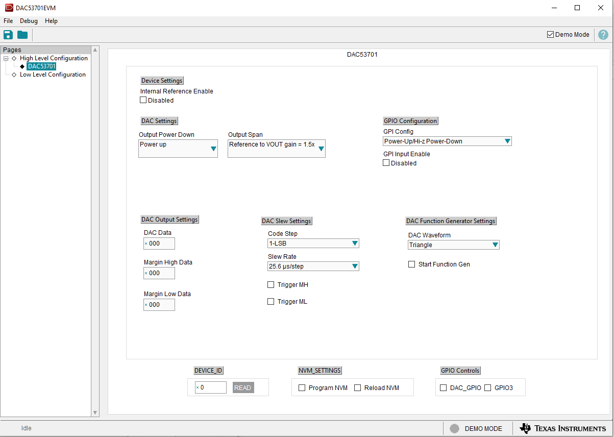
Figure 3-3 shows the High Level Configuration page that provides an interface to quickly configure the parameters and relevant register settings for the respective DACx3701 device. The High Level Configuration page provides an interface to quickly power up, select the reference and output span, and program the output voltage for the respective DACx3701 device. When VDD is applied, the DACx3701 device starts up in Hi-Z power-down mode by default. The High Level Configuration page also provides controls to configure the GPI pin on the respective DACx3701 device, and control the two GPIO outputs of the DAC53701EVM onboard controller. This page provides the settings for the margin-low, margin-high, and nominal DAC outputs. Self-resetting triggers are used to trigger the margin-high and margin-low voltage levels for each DAC channel. The Code Step and Slew Rate drop-down menu settings are also provided on this page to control the slew of each margin high or low trigger (Trigger MH or Trigger ML). The DAC waveform drop-down menu selects the waveform to be generated: triangular, saw-tooth, inverse saw-tooth, or square. The Margin High Code and Margin Low Code settings define the upper and lower bounds of the waveform, respectively. The Start Function Gen checkbox starts or stops the defined function generation. The register settings can be programmed or retrieved using the Program NVM or Reload NVM checkboxes, respectively.
 Figure 3-3 High Level Configuration Page