SLIA086A June 2014 – December 2021 DRV5013 , DRV5013-Q1 , DRV5023 , DRV5023-Q1 , DRV5033 , DRV5033-Q1 , DRV5053 , DRV5053-Q1
4 Digital Hall Sensor Functionality
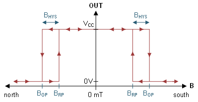
Digital Hall sensors either have an open-drain or push-pull output that pulls low if B exceeds the threshold BOP (the operate point). The output then stays low until B decreases below the threshold BRP (the release point), then the output becomes High-Impedance for an open-drain output and pulled high for a push-pull output. BOP and BRP are always separated with hysteresis (Bhys), which prevents noise-induced toggling at a threshold. Omnipolar devices have an output that reacts to positive and negative fields the same while unipolar devices have an output that reacts to either a positive field or a negative field only.
 Figure 4-1 B-field Response of the DRV5032 Omnipolar Device Variants
Like all data sheet parameters, the actual B thresholds vary due to semiconductor process variation, operating voltage, and temperature.
| PARAMETER | MIN | TYP | MAX | UNIT | |
|---|---|---|---|---|---|
| BOP | Operate point | ±4 | ±7 | ±9.4 | mT |
| BRP | Operate point | ±3 | ±5.6 |
±7.5 |
|
| Bhys | Hysteresis; Bhys = (BOP – BRP) | 0.5 | 1.4 | 3 | |
A magnet and Hall sensor should be selected so that the field at the sensor exceeds the specified max-BOP, to guarantee that the magnetic threshold is crossed.