SLIU024 April 2022 DRV5033 , DRV5033
4.1 Schematics
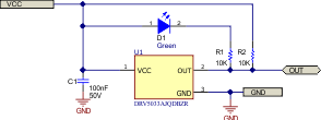
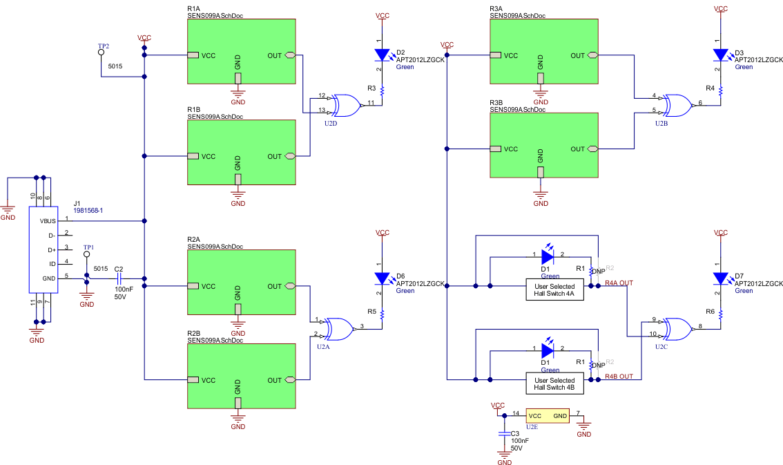
Figure 4-1 and Figure 4-2 show the schematic of the EVM. Figure 4-1 corresponds to the Hall-effect sensor circuit represented by the sheet symbols (green boxes), found in Figure 4-2.
 Figure 4-1 Hall-Effect Switch Circuit
Block
 Figure 4-2 EVM Schematic