SLLA497 September 2020 TMS320F28P550SG , TMS320F28P550SJ , TMS320F28P559SG-Q1 , TMS320F28P559SJ-Q1
4.4 DAB in CLLLC Mode
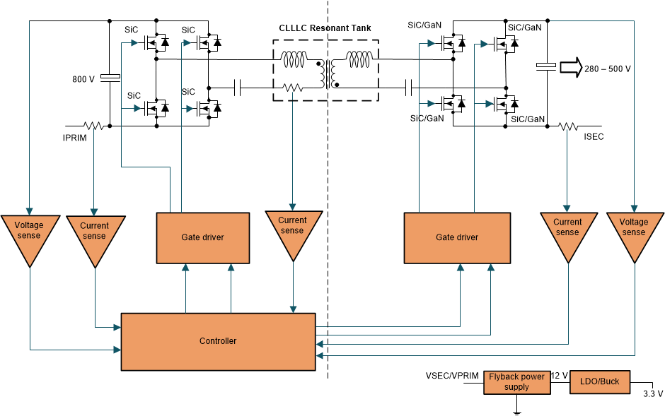
The CLLC incorporates all the functionalities of the LLC described before, but a major advantage of this topology is that with the use of active switches across the secondary, we can obtain bidirectional power transfer as Figure 4-4 shows. The ZVS/ZCS operation of this converter results in increased efficiency. When there is room to vary the bus voltage by a margin of 10%, this converter can cater to wide varying battery voltage with good efficiency performance, but with a fixed bus voltage this has a very limited range of operation. With capacitors in the primary and secondary side of the transformer, the problem of saturation of the core of the transformer is prevented.
 Figure 4-4 DAB- CLLLC Converter.
 This converter is primarily suited for onboard charger applications but can be used at higher power levels upto 10 kW. But scaling to higher power levels and paralleling can be difficult as it requires a highly symmetrical tank structure and synchronization of multiple modules which can be quite difficult. The Bidirectional CLLLC resonant dual active bridge (DAB) reference design for HEV/EV onboard charger TI reference design contains details on the implementation of this converter.